Translate

Tuesday, March 8, 2016

Eagle Transporter


Here are some images MPC/Round 2 models 1/48 scale Eagle Transporter from the television series Space 1999.

From Wikipedia"
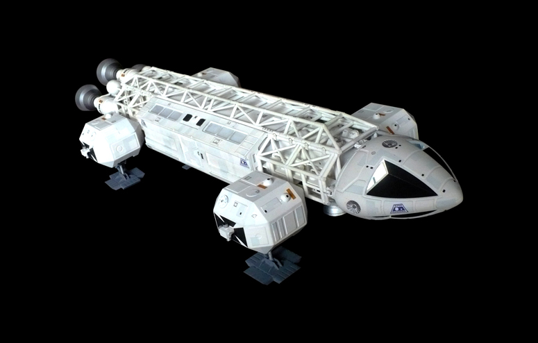
 The Eagle Transporter is a fictional spacecraft seen in the 1970s British television series Space: 1999. The Eagles serve as the primary spacecraft of Moonbase Alpha, which has a fleet of them, and are often used to explore alien planets, defend Moonbase Alpha from attack, and to transport supplies and other items to and from the Moon. The Eagle was designed by Brian Johnson who had worked with Gerry Anderson on Thunderbirds in the mid-1960s and had produced the spacecraft for the 1968 film 2001: A Space Odyssey. The Eagle spacecraft influenced the spaceship designs of Star Wars and other science fiction films and television series.
 The Eagles are constructed by the engineering and technical section of Moonbase Alpha using materials and components either shipped from Earth or manufactured on the Moon.[1] The latter is usually proposed as a rationale for the perceived seemingly endless supply of Eagles despite their frequent losses. At the time of the episode "The Last Sunset", dialogue indicated that there were twenty-eight serviceable Eagles on the roster.
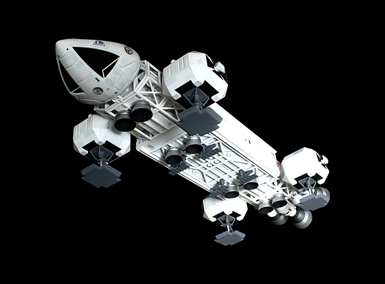
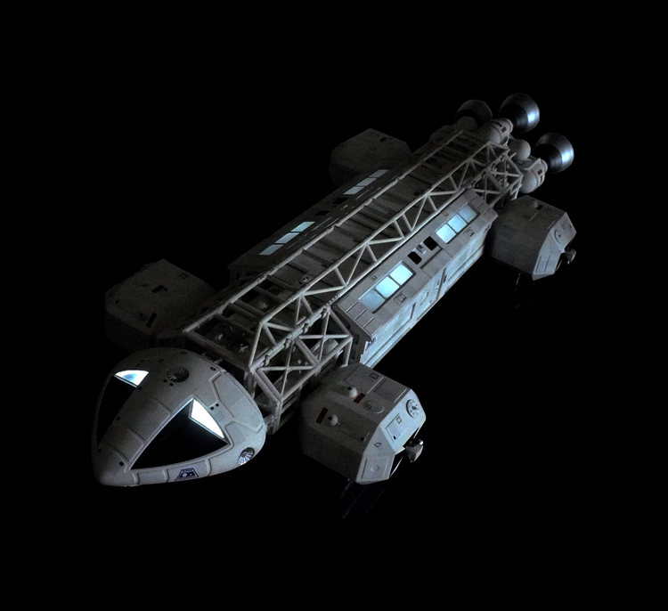
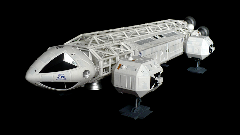
 Completely modular, the craft are divided into three basic sections: the command module, the passenger module/service pod, and the superstructure (containing the landing gear, access corridor/galley, aft compartment, fuel tanks and main propulsion system). The command module also has an escape hatch as revealed in the episode "Devil's Planet", although it is unknown whether this is an original design feature or an adaptation that was designed by Moonbase Alpha. The command module of the Eagle can detach from the main body as seen in the episode "Dragon's Domain" enabling it to dock with another compatible craft or for use as an emergency escape capsule. All Eagles are equipped with artificial gravity.

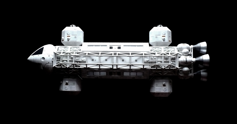
The Eagles are powered by four nuclear fusion rockets and carry fuel reserves for 48 hours (2 days) of flight. Artificial gravity force fields built into the Eagle enable it to accelerate up to 15% of the speed of light, giving it a maximum range (with extra fuel reserves) of several light days. (At 15% of the speed of light, an Eagle would need nearly 7 days to traverse a distance of one light day.) Should there be a need for higher-than-normal velocities, a set of two booster rockets can be fitted to the superstructure to augment the main propulsion system. Under ideal conditions, re-fuelling is carried out in the maintenance hangar at Moonbase; under extraordinary circumstances, provisions for in-flight fuelling are possible.
The Eagle also has the capability to enter the atmosphere of a normal-gravity planetary body, land using its chemically fuelled landing rockets, and take off and return to Moonbase Alpha.[1] The Eagle maintains sufficient fuel for multiple take-offs and landings. Should the craft be required to operate within meta-gravity conditions (take-offs and landings from a high-gravity spatial body), the craft can be equipped with four downward-pointing booster rockets to augment the normal vertical rockets on the craft's undercarriage.
The on-board computer system can handle guidance, astro-navigation, and interpretation of sensor data; for comprehensive data analysis, telemetry is transmitted to Moonbase Main Computer. The craft can also be flown by remote control from Moonbase Alpha.

Although the Eagle was not designed for use as a military vessel, some Eagles on Moonbase Alpha are fitted with a laser emitter as standard equipment and an arsenal of space-to-space missiles. The episode "War Games" suggests that only seven of Alpha's many Eagles are armed at that time. It is demonstrated in the series that Eagles were primarily designed for transport, reconnaissance and scientific surveys. In "War Games" the Eagles are badly outmatched by the Mark IX Hawk, which were designed specifically for combat. The Hawks were faster, more manoeuvrable, and better-armed than the Eagles, although a skilled Eagle pilot such as Alan Carter was still able to destroy several Hawks in the battle to defend Moonbase Alpha.
In addition to the primary weapons mounted on the underside of the Eagle superstructure frame (directly behind the command module)intended for combat or defence when in flight, a retractable laser gun was revealed in Year Two for use when the craft is grounded. This mid-size weapon was mounted on the dorsal surface of the spaceframe and emerged from the girders of the ship's 'backbone'. It can be adjusted to fire in 360 degrees and at numerous angles of elevation. Various pods also carry small arms; a rack of stun-guns and a single laser rifle for the use of crew is mounted by one of the two main hatches.
 Eagles are generally flown by two trained astronauts (Eagle pilots) from the Reconnaissance Section; although the craft can easily be handled by a single pilot, the right seat in the Eagle command module is routinely occupied by an astronaut co-pilot, although this varies according to mission profile. Many non-Reconnaissance personnel on Alpha are former astronauts or have received flight training and are qualified to handle the craft. Eagles can also be piloted by remote control from the Alpha command centre.
 The model of the Eagle used in filming was built in four scales: by the end of the series, there were three 44-inch (110 cm) Eagle models, two 22-inch (56 cm) Eagles, one 11-inch (28 cm) Eagle, and a 5-inch (13 cm) Eagle. The superstructure framework was composed of copper tubing on the larger-scale models and the command module was vacuum-formed plastic. Compressed freon streams were used to portray the vertical jets used in lift-off and landing sequences and, in Year Two, the exhaust from the main rockets. The special effects team worked in Bray Studios, a separate studio away from where the live action filming took place.[citation needed]

The production team included several experts who later went on to win Academy Awards for Alien (1979) and The Empire Strikes Back (1980):

The Eagle became an iconic design in the 1970s, and inspired toys and model kits from various manufacturers. Between 1975 and 1980, Dinky Toys manufactured two well-detailed die-cast Eagle toys, each with different modules and colouring. The Transporter was fairly faithful to the version seen on the show, with the exception of the colouring which consisted of a green main body and a white transporter pod. The Freighter pod, while not accurate to those seen on the show, was inspired by the winch pod. The first edition Freighters came with the main Eagle painted a more correct white, while the waste container carrying pod was painted red. In later editions the Freighter Eagle was changed to blue with a white pod. The Transporter retained the incorrect green/white colour combination for the entire run. Airfix released self-assembly model kits around the same time. In the United States, LJN Toys also manufactured smaller versions in the 1970s, and the company Centuri released a rocket-powered "flying" Eagle Transporter kit. In more recent years, toy/model Eagles have been manufactured by other companies, including Product Enterprise and Iconic Replicas.
The repainted Eagle Transporter was used in the 1980s Polish educational TV series Przybysze z Matplanety ("Visitors from Mathsplanet") as the aliens' spacecraft.
The bulk of an Eagle model was seen as the wreckage of an unknown starship in the Red Dwarf episode "Psirens".

Monday, March 7, 2016

Leonardo Da Vinci's Mechanical Dragonfly

Here are some images of Edu Toy's Leonardo Da Vinci's Mechanical Dragonfly.
The box says "Mechanical Butterfly", though its description and appearance are that of a dragonfly.

From the Instructions"
Da Vinci was the first person to apply himself to the study of animal flight and human flight with such passion. Throughout his life da Vinci dreamt of building a flying machine which would enable man to fly. In spite of being unable to fulfill this task, da Vinci has the distinction of being the first person in the history of human flight to study the subject from a scientific point of view, investigating every possible solution. He even devised plans for muscle powered flying, where the pilot of the machine trys to replicate the beating of a birds wings, gliding, without moving the wings, and mechanical flight, where the machine flies  without a pilot but only thanks but only thanks to the movement of mechanical parts like gears and wings. In his manuscripts da Vinci drew many contraptions, not all of which need a pilot. Many flying machines are preliminary studies, where most of the time da Vinci tried to imitate the anatomy of an animal; a bird, a bat, or an insect, such as a dragonfly. One of the projects for a flying machine with no pilot is the mechanical dragonfly,on folio 1051v of the Codex Atlanticus. da Vinci himself advised where one can admire admire these incredible flying insects: To see four winged flying, look near ditches and you will see dragonflies. It is extremely difficult to create a mechanical replica of the natural movement of an animal. The beating of the dragonfly's four wings is particularly complex and da Vince was well aware of how difficult it would be to create this machine. he himself described it in great detail. It is not simply wings beating up and down; it's a jointed motion. Whilst beating down the wings are "flat" in order to push as much air as possible, whereas when they are raised, they are angled so that they create less resistance. If the dragonfly and therefore da Vinci's machine, was not like this, it would not be able to fly because the power created when the wings beat downwards, would be canceled out when the wings returned to their starting point. Da Vinci wrote: The wings must return to the top very quickly, whereas pushing backwards with the part of the wing which pushes the air must be done at the speed required by the engine each individual time. The movement of each four wings is synchronized with the others. Da Vinci resolved the problem by designing to pairs of wings, one for the front and one for the back, exactly as on a dragonfly. When the wings are beating, the pairs of wings around their main linch-pin. The energy of this movement is provided by two spring loaded motors which drive a mechanical system made by gearwheels, a camshaft and connecting rods which in turn allow the pairs of wings to move alternately and in synchrony. Whilst the wings move more quickly up and down pushing the air, rods of exactly the right length fold the wings downwards ensuring they are angled when they come back up, exactly as it happens in the animal movement. The mechanism is very delicate and in order to make the machine work correctly it must be very fine tuned. Furthermore, the power the motors were able to supply would definitely not have been sufficient to lift the machine off the ground. In spite of this, the machine plan is absolutely fascinating and even if they are too slow, the wings move exactly in the same way as a dragonfly's.

Sunday, March 6, 2016

Leonardo Da Vinci's Ship's Cannon With Shield

Here are some images of Edu Toys Leonardo Da Vinci's Ship's Cannon With Shield.

From the Instructions "

Leonardo da Vinci was also a military engineer; he studied weapons and medieval military techniques at length. A large part of his manuscripts show machines and military architecture, some are copies of machines by Taccola Francesco di Giorgio, others are his own inventions or modifications of existing machines. He also spent a lot of time working on naval battles, designing dozens of ships with as many attacking methods as means of defense on the sea. One of the most original projects is that of the ship with shield and cannon. Da Vinci drew this naval weapon in manuscript B for the first time, almost certainly copying it from a previous author, because the drawing of this project was already presented in the treatises of engineers who came before da Vinci and to whom he referred when studying. Again, it was a general idea, only roughly drawn and without any technical details. Da Vinci subsequently revisited the project; he reconsidered it, improved it and redrew it clearly and in its entirety on folio 172r of the Codex Atlanticus. The idea was to use a small, agile vessel equipped with a cannon. The prow of the ship and the cannon are protected by a wooden shield. Da Vinci studied this subject closely, identified the weak points and invented his own version with many more functions. He transformed the almost "fantastic" medieval drawing into a truly achievable engineering project. First, he concentrated on the structure of the vessel which needed to be reinforced and keep the cannon firmly in the middle. The shield, which previous engineers had shown as being immobile and almost temporary, in da Vinci's drawing was split in two and became part of the structure and mobile. A system of ropes and pulleys keeps the shields raised to protect the ship. Once the winches are locked, the weight of the shields themselves causes them to rotate outwards to uncover the cannon which can then fire. The shield rotate on two non-parallel axes and da Vinci designed a geometric shape of them so that when lowered, they fit around the curve of the ship. The resulting contact between hull and shield is not an easy line to calculate and da Vinci proposed a few variations. Firing the cannon is another problem to deal with, as this causes a recoil powerful enough to push the ship backwards. The semi-submerged shields themselves act as breaks, keeping the ship steady as it fires. Da Vinci's drawing on folio 172r even shows the metal covered prow of the ship with a detail showing the device that attaches the shield hinges. The metal covered prow is there to deliver the first blow to the enemy and is therefore a secondary weapon. The shields are not just to protect the prow, but also to hide the main weapon: the cannon. The ship could therefore approach the enemy quickly, and its tapered and futuristic shape made it also rather menacing. It was protected by a shield which made the cannon invisible and meant that enemy weapons would be ineffective work. The angle of the shield was also useful to deflect cannon fire. When rammed quickly into the enemy, it could create the first serious damage thanks to its metal covered prow. Once the enemy ship was "hooked' and presumably a breach had been created in the hull, it was the moment to unveil the secret weapon. The shields having been quickly lowered thanks to their own weight, the cannon was ready to fire directly into the enemy ship. In theory, a small vessel such as this could therefore sink a large galleon. It is not known whether a ship like this was ever built. There are no records of it and perhaps this project too remained amongst the many projects that Leonardo da Vinci never carried out.  

Thursday, March 3, 2016

Vickers Machine Gun

Here are some images of Williams Brothers 1/6 scale Vickers Machine Gun. With a bit of extra scratch work from yours truly.

From Wikipedia"

The Vickers machine gun or Vickers gun is a name primarily used to refer to the water-cooled .303 British (7.7 mm) machine gun produced by Vickers Limited, originally for the British Army. The machine gun typically required a six to eight-man team to operate: one fired, one fed the ammunition, the rest helped to carry the weapon, its ammunition and spare parts. It was in service from before the First World War until the 1960s, with air-cooled versions of it on many Allied World War I fighter aircraft.
The weapon had a reputation for great solidity and reliability. Ian V. Hogg, in Weapons & War Machines, describes an action that took place in August 1916, during which the British 100th Company of the Machine Gun Corps fired their ten Vickers guns continuously for twelve hours. Using 100 barrels, they fired a million rounds without a failure. "It was this absolute foolproof reliability which endeared the Vickers to every British soldier who ever fired one."

The Vickers machine gun was based on the successful Maxim gun of the late 19th century. After purchasing the Maxim company outright in 1896, Vickers took the design of the Maxim gun and improved it, reducing its weight by lightening and simplifying the action and substituting components made with high strength alloys. A muzzle booster was also added.
The British Army formally adopted the Vickers gun as its standard machine gun on 26 November 1912, using it alongside their Maxims. There were still great shortages when the First World War began, and the British Expeditionary Force was still equipped with Maxims when sent to France in 1914. Vickers was, in fact, threatened with prosecution for war profiteering, due to the exorbitant price it was demanding for each gun. As a result, the price was slashed. As the war progressed, and numbers increased, it became the British Army's primary machine gun, and served on all fronts during the conflict. When the Lewis Gun was adopted as a light machine gun and issued to infantry units, the Vickers guns were redefined as heavy machine guns, withdrawn from infantry units, and grouped in the hands of the new Machine Gun Corps (when heavier 0.5 in/12.7 mm calibre machine guns appeared, the tripod-mounted, rifle-calibre machine guns like the Vickers became medium machine guns). After the First World War, the Machine Gun Corps (MGC) was disbanded and the Vickers returned to infantry units. Before the Second World War, there were plans to replace the Vickers gun; one of the contenders was the 7.92 mm (.312 in) Besa machine gun (a Czech design), which eventually became the British Army's standard tank-mounted machine gun. However, the Vickers remained in service with the British Army until 30 March 1968. Its last operational use was in the Radfan during the Aden Emergency. Its successor in UK service is the L7 GPMG

In 1913, a Vickers machine gun was mounted on the experimental Vickers E.F.B.1 biplane, which was probably the world's first purpose-built combat aeroplane. However, by the time the production version, the Vickers F.B.5, had entered service the following year, the armament had been changed to a Lewis gun.
During World War I, the Vickers gun became a standard weapon on British and French military aircraft, especially after 1916. Although heavier than the Lewis, its closed bolt firing cycle made it much easier to synchronize to allow it to fire through aircraft propellers. The belt feed was enclosed right up to the gun's feed-way to inhibit effects from wind. Steel disintegrating-link ammunition belts were perfected in the UK by William de Courcy Prideaux in mid-war and became standard for aircraft guns thereafter. The famous Sopwith Camel and the SPAD XIII types used twin synchronized Vickers, as did most British and French fighters between 1918 and the mid-1930s. In the air, the weighty water cooling system was rendered redundant by the chilly temperatures at high altitude and the constant stream of air passing over the gun as the plane flew; but because the weapon relied on barrel recoil, the (empty) water-holding barrel jacket or casing needed to be retained. Several sets of louvred slots were cut into the barrel jacket to aid air cooling, a better solution than what had initially been attempted with the 1915-vintage lMG 08 German aircraft ordnance.
As the machine gun armament of fighter aircraft moved from the fuselage to the wings in the years before the Second World War, the Vickers was generally replaced by the faster-firing Browning Model 1919 using metal-linked cartridges. The Gloster Gladiator was the last RAF fighter to be armed with the Vickers, although they were later replaced by Brownings. The Fairey Swordfish continued to be fitted with the weapon until production ended in August 1944.
Several British bombers and attack aircraft of the Second World War mounted the Vickers K machine gun or VGO, a completely different design, resembling the Lewis gun in external appearance.

Tuesday, March 1, 2016

Wright Flyer

Here are some images of Revell's 1/39 scale Wright Flyer.
One would think that the years this kit has been around, Revell would fixed the rigging instructions for this kit by now. If there ever was a subject that needs to be done in a high tech kit it's the Wright flyer.
To be more accurate extra rigging has to be placed between the front and back pillars respectively. Like what you would see on a Spad.

From Wikipedia"

The Wright Flyer (often retrospectively referred to as Flyer I or 1903 Flyer) was the first successful heavier-than-air powered aircraft. It was designed and built by the Wright brothers. They flew it four times on December 17, 1903, near Kill Devil Hills, about four miles south of Kitty Hawk, North Carolina, US. Today, the airplane is exhibited in the National Air and Space Museum in Washington D.C.
The U.S. Smithsonian Institution describes the aircraft as "the first powered, heavier-than-air machine to achieve controlled, sustained flight with a pilot aboard." The flight of Flyer I marks the beginning of the "pioneer era" of aviation.

The Flyer was based on the Wrights' experience testing gliders at Kitty Hawk between 1900 and 1902. Their last glider, the 1902 Glider, led directly to the design of the Flyer.
The Wrights built the aircraft in 1903 using giant spruce wood as their construction material. The wings were designed with a 1-in-20 camber. Since they could not find a suitable automobile engine for the task, they commissioned their employee Charlie Taylor to build a new design from scratch, effectively a crude gasoline engine.[3] A sprocket chain drive, borrowing from bicycle technology, powered the twin propellers, which were also made by hand.
The Flyer was a canard biplane configuration. As with the gliders, the pilot flew lying on his stomach on the lower wing with his head toward the front of the craft in an effort to reduce drag. He steered by moving a cradle attached to his hips. The cradle pulled wires which warped the wings and turned the rudder simultaneously.
The Flyer's "runway" was a track of 2x4s stood on their narrow edge, which the brothers nicknamed the "Junction Railroad".
 The Flyer was conceived as a control-canard, as the Wrights were more concerned with control than stability. However it was found to be so highly unstable it was barely controllable. Following the first flight, ballast was added to the nose to move the center of gravity forward and reduce pitch instability. However the basics of pitch stability of the canard configuration were not understood by the Wright Brothers. F.E.C. Culick stated, "The backward state of the general theory and understanding of flight mechanics hindered them... Indeed, the most serious gap in their knowledge was probably the basic reason for their unwitting mistake in selecting their canard configuration".

Upon returning to Kitty Hawk in 1903, the Wrights completed assembly of the Flyer while practicing on the 1902 Glider from the previous season. On December 14, 1903, they felt ready for their first attempt at powered flight. With the help of men from the nearby government life-saving station, the Wrights moved the Flyer and its launching rail to the incline of a nearby sand dune, Big Kill Devil Hill, intending to make a gravity-assisted takeoff. The brothers tossed a coin to decide who would get the first chance at piloting, and Wilbur won. The airplane left the rail, but Wilbur pulled up too sharply, stalled, and came down in about three seconds with minor damage.
Repairs after the abortive first flight took three days. When they were ready again on December 17, the wind was averaging more than 20 mph, so the brothers laid the launching rail on level ground, pointed into the wind, near their camp. This time the wind, instead of an inclined launch, helped provide the necessary airspeed for takeoff. Because Wilbur already had the first chance, Orville took his turn at the controls. His first flight lasted 12 seconds for a total distance of 120 ft (36.5 m) – shorter than the wingspan of a Boeing 747, as noted by observers in the 2003 commemoration of the first flight.
Taking turns, the Wrights made four brief, low-altitude flights that day. The flight paths were all essentially straight; turns were not attempted. Each flight ended in a bumpy and unintended "landing". The last flight, by Wilbur, was 852 feet (260 m) in 59 seconds, much longer than each of the three previous flights of 120, 175 and 200 feet. The landing broke the front elevator supports, which the Wrights hoped to repair for a possible four-mile (6 km) flight to Kitty Hawk village. Soon after, a heavy gust picked up the Flyer and tumbled it end over end, damaging it beyond any hope of quick repair. It was never flown again.
 In 1904, the Wrights continued refining their designs and piloting techniques in order to obtain fully controlled flight. Major progress toward this goal was achieved with a new Flyer in 1904 and even more decisively in 1905 with a third Flyer, in which Wilbur made a 39-minute, 24-mile (39 km) nonstop circling flight on October 5. While the 1903 Flyer was clearly a historically important test vehicle, its hallowed status in the American imagination has obscured the role of its two successors in the continuing development that led to the Wrights' mastery of controlled powered flight in 1905.