Monday, June 30, 2014

George Adamski's Flying Saucer

Here are some images of Atlantis's 1/60 scale (yes they know the scale) George Adamski's Flying Saucer.
And now Ladies and Gentlemen, it is time to break out the tinfoil hats.

From Wikipedia"
George Adamski (April 17, 1891 – April 23, 1965) was a Polish-born American citizen who became widely known in ufology circles, and to some degree in popular culture, after he claimed to have photographed ships from other planets, met with friendly Nordic alien Space Brothers, and to have taken flights with them. The first of the so-called contactees of the 1950s, he was called a "philosopher, teacher, student and saucer researcher," though his claims were met with skepticism.

On October 9, 1946, during a meteor shower, Adamski and some friends claimed that while they were at the Palomar Gardens campground, they witnessed a large cigar-shaped "mother ship." In 1947, Adamski took a photograph of what he claimed was the 1946 cigar-shaped "mother ship" crossing in front of the moon over Palomar Gardens.
On May 29, 1950, Adamski took a photograph of what he alleged to be six unidentified objects in the sky, which appeared to be flying in formation. Adamski's May 29, 1950, UFO photograph was depicted in an August 1978 commemorative stamp issued by the island nation of Grenada in order to mark the "Year of UFOs."
On November 20, 1952, Adamski and several friends were in the Colorado Desert near the town of Desert Center, California, when they purportedly saw a large submarine-shaped object hovering in the sky. Believing that the ship was looking for him, Adamski is said to have left his friends and to have headed away from the main road. Shortly afterwards, according to Adamski's accounts, a scout ship made of a type of translucent metal landed close to him, and its pilot, a Venusian called Orthon, disembarked and sought him out.

Adamski's photograph, which is said to be of an UFO, taken on December 13, 1952. However, German scientist Walther Johannes Riedel said this photo was a fake, and that the landing struts were light bulbs
 
Adamski described Orthon as being a medium-height humanoid with long blond hair and tanned skin wearing reddish-brown shoes, though, as Adamski added, "his trousers were not like mine." Adamski said Orthon communicated with him via telepathy and through hand signals. During their conversation, Orthon is said to have warned of the dangers of nuclear war and to have arranged for Adamski to be taken on a trip to see the Solar System, including the planet Venus, the location where Mrs. Adamski had been reincarnated. Adamski said that Orthon had refused to allow himself to be photographed and instead asked Adamski to provide him with a blank photographic plate, which Adamski says that he gave him. When Orthon left, Adamski said that he and George Hunt Williamson were able to take plaster casts of Orthon's footprints, which contained mysterious symbols.
Orthon is said to have returned the plate to Adamski on December 13, 1952, at which point it was found to contain new strange symbols. It was during this meeting that Adamski is said to have taken a now famous UFO photograph using his 6-inch (150 mm) telescope.
In 1954, Desmond Leslie is said to have witnessed several UFOs with Adamski while visiting him in California. He described one of them in a letter he sent to his wife while he was in San Diego:
... a beautiful golden ship in the sunset, but brighter than the sunset ... It slowly faded out, the way they do.
In 1957 Adamski received a letter signed "R.E. Straith," alleged representative of the "Cultural Exchange Committee" of the U.S. State Department. The letter said the U.S. Government knew that Adamski had spoken to extraterrestrials in a California desert in 1952, and that a group of highly placed government officials planned on public corroboration of Adamski's story. Adamski was proud of this endorsement and exhibited it to support his claims. However, in 2002 ufologist James W. Moseley revealed that the letter was a hoax. Moseley said he and his friend Gray Barker had obtained some official State Department letterheads, created the R.E. Straith persona, and then written the letter to Adamski as a prank. According to Moseley, the FBI investigated the case and discovered that the letter was a hoax, but charges were not filed against Moseley or Barker. Moseley also wrote that the FBI informed Adamski that the Straith letter was a hoax and asked him to stop using it as evidence in support of his claims, but that Adamski refused and continued to display the letter in his lectures and talks.
In May 1959, Adamski received a letter from the head of the Dutch Unidentified Flying Objects Society informing him that she had been contacted by officials at the palace of Queen Juliana of the Netherlands and "that the Queen would like to receive you." Adamski informed a London newspaper about the invitation, which prompted the court and cabinet to request that the queen cancel her private audience with Adamski, but the queen went ahead with the audience, saying, "A hostess cannot slam the door in the face of her guests." After the audience, Dutch Aeronautical Association president Cornelis Kolff said, "The Queen showed an extraordinary interest in the whole subject." Wire services such as United Press International and Reuters sent the story out, and newspapers around the world ran it. On May 19, 1959, The Straits Times ran the story. The Sydney Morning Herald ran it on May 20, 1959, along with an image titled "The 'Moon Man.'" On May 21, 1959, the Rockford Register-Republic ran the article, and the Los Angeles Times ran it on May 27, 1959.[
Adamski believed that the photographs of the far side of the Moon that were taken by the Soviet lunar probe Luna 3 in 1959 were altered to depict a barren, lifeless surface when in fact there were cities, trees, and snow-capped mountains there instead.

Da Vinci Flying Machine

Here are some images of Academy's Da Vinci Flying Machine.
A very simple model but fun. The wings flap when you wind it up.

Sunday, June 29, 2014

Da Vinci Clock

Here are some images of Academy's Da Vinci Clock.
So far as I can tell this so far is the best of the Academy Leonardo Da Vinci kits, and it work to.
You can get up to 1 hour out of it before rewinding.

From Leonardo Da Vinci Inventions"

To put away any initial confusion – Leonardo da Vinci did not invent the clock. What he did was design a more accurate clock.
While clocks that showed hours and minutes had become increasingly accurate in da Vinci’s time (the 15th century), they didn’t really make a big leap forward until the incorporation of the pendulum about 200 years later. But, da Vinci actually designed a more accurate clock in his lifetime.
Leonardo’s clock had two separate mechanisms: one for minutes and one for hours. Each was made up of elaborately connected weights, gears and harnesses. The clock also has a dial for keeping track of moon phases.
Da Vinci’s major innovation was to have springs, rather than weights operate his clock. He also included the detail of some materials that would be used to make the clock – including diamonds and rocks.

Thursday, June 26, 2014

Pfalz D III


Here are some more images of Eduard's 1/48 scale Pfalz DIII.

From Wikipedia"
 The Pfalz D.III was a fighter aircraft used by the Luftstreitkräfte (Imperial German Air Service) during the First World War. The D.III was the first major original design from Pfalz Flugzeugwerke. Though generally considered inferior to contemporary Albatros and Fokker fighters, the D.III was widely used by the Jagdstaffeln from the fall of 1917 through the summer of 1918. It continued to serve as a training aircraft until the end of the war.
Prior to World War I, Pfalz Flugzeugwerke produced Morane-Saulnier monoplane designs under license. These aircraft entered military service as the Pfalz A- and E-series. In September 1916, Pfalz began producing the first of 20 Roland D.I and 200 Roland D.II fighters under license.
In November 1916, Pfalz hired Rudolph Gehringer from Flugzeugbau Friedrichshafen GmbH. As Pfalz’s new chief engineer, Gehringer immediately commenced work on an original fighter design. The resulting D.III emerged in April 1917. Like the Rolands, the D.III used a plywood monocoque fuselage. Two layers of thin plywood strips were placed over a mold to form one half of a fuselage shell. The fuselage halves were then glued together, covered with a layer of fabric, and doped. This Wickelrumpf method gave the fuselage great strength, light weight, and smooth contours compared to conventional construction techniques. However, it also proved to be more labor intensive and expensive. Furthermore, the D.III fuselage was prone to twisting or warping from side to side as it aged, a defect variously attributed to the use of insufficiently seasoned wood or to moisture absorption in damp conditions.
The wings were of conventional construction, with a flush Teves und Braun radiator offset to the right side of the upper wing. The ailerons were of wooden construction, rather than the more conventional steel tube construction. The horizontal stabilizer had an inverted airfoil section, which facilitated dive recovery and permitted the use of an unbalanced elevator.
The Idflieg found the prototype promising. It directed Pfalz to halt production of the Roland D.III and to complete the balance of the contract, 70 aircraft, to the new design. After a Typenprüfung (type test) at Adlershof in May, the Idflieg ordered various modifications, including an enlarged rudder and horn-balanced ailerons. In June 1917, Pfalz received a second order for 300 aircraft.


Deliveries to operational units began in August 1917. Jasta 10 was the first recipient of the new aircraft, followed by Jasta 4. While markedly better than the earlier Roland designs, the D.III was generally considered inferior to the Albatros D.III and D.V. German pilots variously criticized the Pfalz’s heavy controls, low speed, lack of power, or low rate of climb compared to the Albatros. The D.III slipped in turns, leading to crashes when unwary pilots turned at very low altitudes. Moreover, the Pfalz stalled sharply and spun readily. Recovery from the resulting flat spin was difficult, though some pilots took advantage of this trait to descend quickly or evade enemy aircraft.
The Pfalz’s primary advantage was its strength and sturdiness. The Albatros scouts were plagued by failure of their single-spar lower wings. The Pfalz, however, could safely dive at high speeds due to its twin-spar lower wing. For this reason, the Pfalz was well-suited to diving attacks on observation balloons, which were usually heavily defended by anti-aircraft guns trained to the balloon's altitude.
The most pressing complaint about the new Pfalz was that the guns were buried in the fuselage, preventing pilots from clearing gun jams in flight. This feature had been carried over from the earlier Roland designs. In November 1917, Pfalz responded by producing the slightly modified D.IIIa, which relocated the guns to the upper fuselage decking. The D.IIIa was distinguishable by its enlarged semicircular horizontal stabilizer and cropped lower wingtips. It also featured a more powerful version of the Mercedes D.III engine.
Pfalz built approximately 260 D.III and 750 D.IIIa aircraft. Most were delivered to Bavarian Jastas. Once Pfalz completed the final batch in May 1918, production shifted to the D.IIIa's successor, the D.XII. Some aircraft from the final D.IIIa batch were delivered to Turkey.
As of 30 April 1918, 433 D.IIIa scouts were still in frontline use. By 31 August, that number had declined to 166. Many serviceable aircraft were sent to advanced training schools, but approximately 100 aircraft remained in frontline use at the time of the Armistice.
 Today, there are no known surviving D.III airframes. However, two flying replicas were built for the 1966 film The Blue Max. One replica was built from scratch, while a second was converted from a de Havilland Tiger Moth airframe. Both replicas are currently based in New Zealand.

Tuesday, June 24, 2014

Royal Aircraft Factory S.E.5.A.

Here are some images of Eduard's 1/48 scale Royal Aircraft Factory's S.E.5.A. From Wikipedia "The Royal Aircraft Factory S.E.5 was a British biplane fighter aircraft of the First World War. Although the first examples reached the Western Front before the Sopwith Camel and it had a much better overall performance, problems with its Hispano-Suiza engine meant that there was a chronic shortage of S.E.5s until well into 1918 and fewer squadrons were equipped with the type than with the Sopwith fighter. Together with the Camel, the S.E.5 was instrumental in regaining allied air superiority in mid-1917 and maintaining this for the rest of the war, ensuring there was no repetition of "Bloody April" 1917 when losses in the Royal Flying Corps were much heavier than in the Luftstreitkräfte.

Monday, June 23, 2014

Diesel Tugboat

Here are some images of Lindberg Models 1/87 scale Diesel Tugboat.

From Wikipedia"
 A tugboat (tug) is a boat that maneuvers vessels by pushing or towing them. Tugs move vessels that either should not move themselves, such as ships in a crowded harbor or a narrow canal, or those that cannot move by themselves, such as barges, disabled ships, or oil platforms. Tugboats are powerful for their size and strongly built, and some are ocean-going. Some tugboats serve as icebreakers or salvage boats. Early tugboats had steam engines, but today have diesel engines. Many tugboats have firefighting monitors, allowing them to assist in firefighting, especially in harbors.

Tugboat engines typically produce 500 to 2,500 kW (~ 680 to 3,400 hp), but larger boats (used in deep waters) can have power ratings up to 20,000 kW (~ 27,200 hp) and usually have an extreme power:tonnage-ratio (normal cargo and passenger ships have a P:T-ratio (in kW:GRT) of 0.35 to 1.20, whereas large tugs typically are 2.20 to 4.50 and small harbour-tugs 4.0 to 9.5). The engines are often the same as those used in railroad locomotives, but typically drive the propeller mechanically instead of converting the engine output to power electric motors, as is common for diesel-electric locomotives. For safety, tugboats' engines often feature two of each critical part for redundancy.
A tugboat's power is typically stated by its engine's horsepower and its overall bollard pull.
Tugboats are highly maneuverable, and various propulsion systems have been developed to increase maneuverability and increase safety. The earliest tugs were fitted with paddle wheels, but these were soon replaced by propeller-driven tugs. Kort nozzles have been added to increase thrust per kW/hp. This was followed by the nozzle-rudder, which omitted the need for a conventional rudder. The cycloidal propeller was developed prior to World War II and was occasionally used in tugs because of its maneuverability. After WWII it was also linked to safety due to the development of the Voith Water Tractor, a tugboat configuration which could not be pulled over by its tow. In the late 1950s, the Z-drive or (azimuth thruster) was developed. Although sometimes referred to as the Schottel system, many brands exist: Schottel, Z-Peller, Duckpeller, Thrustmaster, Ulstein, Wärtsilä, Berg Propulsion, etc. These propulsion systems are used on tugboats designed for tasks such as ship docking and marine construction. Conventional propeller/rudder configurations are more efficient for port-to-port towing.
The Kort nozzle is a sturdy cylindrical structure around a special propeller having minimum clearance between the propeller blades and the inner wall of the Kort nozzle. The thrust:power ratio is enhanced because the water approaches the propeller in a linear configuration and exits the nozzle the same way. The Kort nozzle is named after its inventor, but many brands exist.
A recent Dutch innovation is the Carousel Tug, winner of the Maritime Innovation Award at the Dutch Maritime Innovation Awards Gala in 2006. The Carousel Tug adds a pair of interlocking rings to the body of the tug, the inner ring attached to the boat, with the outer ring attached to the towed ship by winch or towing hook. Since the towing point rotates freely, the tug is very difficult to capsize.
The Voith Schneider propeller (VSP), also known as a cycloidal drive is a specialized marine propulsion system. It is highly maneuverable, being able to change the direction of its thrust almost instantaneously. It is widely used on tugs and ferries.
From a circular plate, rotating around a vertical axis, a circular array of vertical blades (in the shape of hydrofoils) protrude out of the bottom of the ship. Each blade can rotate itself around a vertical axis. The internal gear changes the angle of attack of the blades in sync with the rotation of the plate, so that each blade can provide thrust in any direction, very similar to the collective pitch control and cyclic in a helicopter.

Sunday, June 22, 2014

XP-34 Landspeeder

Here are some more images of Revell's 1/25 scale XP-34 Landspeeder from Star Wars.
I don't know about you but doesn't the Luke Skywalker figure look suspiciously like Chuck Norris? But I digress.
As has been stated before what one does to any snaptite pre painted kit worth its salt is to of course glue it and add more paint to it which is what has been done here.
Things added to this model is of course more dirt, scratches and dents. I also added a couple of instrument panels to the interior plus more detailing on whatever that thing is on the hood.

From Wikipedia"
Landspeeders are fictional antigravity craft used through the Star Wars movies and Star Wars Expanded Universe. They are depicted both in civilian and military capacities, and several versions have been merchandised as toys and models.
Landspeeders first appear in Star Wars Episode IV: A New Hope. Two of them—Luke Skywalker's (Mark Hamill) XP-34 and a V-35—were designed by Special Effects genius John Stears and were fitted around cars; Skywalker's landspeeder was built around a small sports car manufactured by Ogle Design. One of the major challenges the production crew faced was disguising the wheels to create the illusion that the craft was hovering.[2][3] For certain shots, they shot from camera angles that masked the wheels; for long-distance shots, they used reflective material, gelatin on the camera lens, and shadow effects. A small blur could be seen under the speeder, which George Lucas called "The Force Spot" (stated in Special Edition Tape). Production designer Roger Christian used an angled mirror and a broom attached to the vehicle's underside to create, at certain angles, the illusion that the craft was hovering and kicking up dust. Star Wars creator George Lucas used digital technology to enhance the landspeeder effects in the Special Edition of A New Hope. Industrial Light and Magic's (ILM) Doug Chiang design the Naboo Flash speeder with a "race car look" while the Gian speeder's appearance is ILM's response to Lucas' request that the Naboo troops have "a pick-up truck with guns."
Expanded Universe material describes speeders as using a "repulsorlift" that allows them to travel above a world's surface; a key differentiating point between landspeeders and airspeeders is the altitude the repulsorlift allows the craft to reach. In A New Hope, Luke Skywalker (Mark Hamill) sells his landspeeder in order to pay Han Solo (Harrison Ford) to take him, Obi-Wan Kenobi (Alec Guinness), C-3PO (Anthony Daniels), and R2-D2 (Kenny Baker) to Alderaan. Naboo security forces use landspeeders in their attempt to retake the capital city of Theed in Star Wars Episode I: The Phantom Menace, and various speeders appear in Star Wars Episode II: Attack of the Clones and Star Wars Episode III: Revenge of the Sith. Speeders are playable-controllable craft in a variety of LucasArts titles.

Friday, June 20, 2014

Fokker E.II Eindecker


Here are some more images of Eduard's 1/48 scale Fokker E.II Eindecker.
From Wikipedia "
The Fokker E.II was the second variant of the German Fokker Eindecker single-seat monoplane fighter aircraft of World War I. The E.II was essentially a Fokker E.I with the 75 kW (100 hp) Oberursel U.I 9-cylinder rotary engine, a close copy of the French Gnôme Monosoupape rotary of the same power output, in place of the E.I's 60 kW (80 hp) Oberursel U.0, but whereas the E.I was simply a M.5K with a 7.92 mm (.312 in) machine gun bolted to it, the E.II was designed with the weapon system integrated with its airframe.

On 13 June 1915, Anthony Fokker demonstrated the first E.II to an audience of German commanders, including Crown Prince Wilhelm of Germany, at a German Fifth Army airfield. On 23 and 24 June he demonstrated the aircraft at Douai to the German Sixth Army. It was during these demonstrations, only one week before any kills would be achieved in the Eindecker type, that Fokker himself attempted to engage an enemy aircraft but he was unable to find a target.
The major difference between the types was a reduced wingspan on the E.II, intended to increase speed, but handling and climbing performance suffered. The type was therefore quickly superseded by the E.III. The E.II also had a larger fuel capacity, 66 kg (145 lb) to the E.I's 50 kg (110 lb). As with the M.5K/MG quintet of prototype Eindeckers, the pilot was provided with a head support to help him resist the airstream when he had to raise his head to use the gun sights.
The heavier weight of the 75 kW (100 hp) Oberursel U.I rotary engine used to power the E.II necessitated both a somewhat lengthened rear fuselage structure, in comparison to the E.I version to achieve proper balance, with the U.I engine's larger diameter requiring a larger radius "horseshoe" pattern cowl to enclose it, and the aluminum upper deck of the nose was raised along with it - resulting in metal soffits having to be fitted where the upper deck met the upper longerons, with additional structural metal tubing additions to the forward ends of the upper longerons immediately behind the firewall to support the "soffits" and sides of the raised upper nose panel. This format was continued with the E.III.
The E.II was built in parallel with the E.I and the choice of whether an airframe became an E.I or E.II depended on the availability of engines. In total, Fokker production figures state that 49 E.IIs were built and 45 of these had been delivered to the Western Front Fliegertruppe by December 1915 (Luftstreitkräfte from October 1916 onwards) at which time production switched to the main Eindecker variant, the Fokker E.III, which used the same 75 kW (100 hp) Oberursel U.I engine. Some E.IIs under production were completed as E.IIIs and numerous E.IIs returned to Fokker's factory for repair were upgraded to E.III specification.

Unmanned Soviet Recon Probe

Here are some more images of my scratchbuilt Unmanned Soviet Recon Probe from the movie 2010 Odyssey Two "The Year We Make Contact". Scale 1" for every 1m.
I built this model based from the old L miller plan drawings from the late 80's
Researching this model was difficult. I could find no usable photos from the Interweb and it is barely visible when it makes its appearance in the film. More silhouette and shadow than anything.
So when it came to colours and markings I was relegated imagination and guess work. Though I realize not entirely accurate.
Still I think it turned out pretty well.
A technical error I noticed about this design is that there doesn't appear to be any side thrusters. Oh well it's only a movie.
The stencil work were taken from decals left over from the Testors Mig Ferret kit and a German tank model..

Specifications:
Weight: 6390 lbs
Speed: 35ft/sec2
Range: 500,000 MI
Engines: Chemical Rockets
Weapons: None
Defenses: None
Capable of Planet Fall.

From Wikipedia"
2010 (also known as 2010: The Year We Make Contact) is a 1984 American science fiction film written and directed by Peter Hyams. It is a sequel to Stanley Kubrick's 1968 film 2001: A Space Odyssey, and is based on Arthur C. Clarke's novel 2010: Odyssey Two, a literary sequel to the film.
Roy Scheider, Helen Mirren, Bob Balaban and John Lithgow star, along with Keir Dullea and Douglas Rain of the cast of the previous film.
When Clarke published his novel 2010: Odyssey Two in 1982, he telephoned Stanley Kubrick, and jokingly said, "Your job is to stop anybody [from] making it [into a movie] so I won't be bothered." Metro-Goldwyn-Mayer (MGM) subsequently worked out a contract to make a film adaptation, but Kubrick had no interest in directing it. However, Peter Hyams was interested and contacted both Clarke and Kubrick for their blessings:
I had a long conversation with Stanley and told him what was going on. If it met with his approval, I would do the film; and if it didn't, I wouldn't. I certainly would not have thought of doing the film if I had not gotten the blessing of Kubrick. He's one of my idols; simply one of the greatest talents that's ever walked the Earth. He more or less said, 'Sure. Go do it. I don't care.' And another time he said, 'Don't be afraid. Just go do your own movie.
While he was writing the screenplay in 1983, Hyams (in Los Angeles) began communicating with Clarke (in Sri Lanka) via the then-pioneering medium of e-mail. The two would discuss the planning and production of the film on an almost daily basis using this method. Their correspondence was published in 1984 as The Odyssey File: The Making of 2010. The book illustrates Clarke's fascination with the new method of communication, and also includes Clarke's list of the top science fiction films ever made. In order to give the publishers enough lead-time to have it available for the release of the movie, the book terminates while the movie is still in pre-production. At the point of the last e-mail, Clarke had not yet read the script, and Roy Scheider was the only actor who had been cast.
Principal photography on the film began in February 1984 for a 71 day schedule. The majority of the film was shot on MGM's soundstages in Los Angeles, with the exception of a week of location work in Washington DC, Rancho Palos Verdes, California, and at the Very Large Array in New Mexico.


The special effects for 2010 were filmed on 65mm film (the live action scenes were filmed on 35mm) and, due to the differences in film size and ratio, there is a noticeable "cut off" area at the side of the picture during the space scenes when the film is viewed in widescreen. The effects were produced by the Entertainment Effects Group (EEG), the special effects house created by Douglas Trumbull. However, Trumbull himself did not work on the film, and the effects were supervised by Richard Edlund, who had just left Industrial Light & Magic. After completing 2010, EEG would become a part of Edlund's own effects company Boss Film Corporation.
Early in the production of 2010, Hyams had learned that all of the original large spacecraft models from "2001", including the original 50-foot model of the "Discovery One", had been destroyed following the filming, as ordered by Kubrick, as had all of the original model-makers' designs for building the "Discovery One". Consequently, the model-makers at EEG had to use frame-by-frame enlargements from a 70mm copy of "2001" to recreate the original large "Discovery One" model. The "Leonov" spacecraft, as well as several of its interior crew areas and other elements of the spacecraft's advanced technology, were designed by the noted conceptual artist Syd Mead.
Although computer-generated imagery (or CGI) was still in an early phase of development in 1984, the special effects team of 2010 used CGI to create the dynamic-looking cloudy atmosphere of the planet Jupiter, as well as the swarm of monoliths that engulf the planet and turn it into a Sun for the planet Europa. Digital Productions would use data supplied by the Jet Propulsion Laboratory to create the turbulent Jovian atmosphere. This was one of the first instances of what the studio would later refer to as "Digital Scene Simulation", a concept they would take to the next level with The Last Starfighter.
In order to maintain the realism of the lighting in outer space, in which light would usually come from a single light source (in this case, the Sun), Edlund and Hyams decided that blue-screen photography would not be used for shooting the space scenes. Instead, a process known as front-light/back-light filming was used. The models were filmed as they would appear in space, then a white background was placed behind the model and the first pass was repeated. This isolated the model's outlines so that proper traveling mattes could be made. All of this processing doubled the amount of time that it took to film these sequences, due to the additional motion-control pass that was needed to generate the matte. This process also eliminated the problem of "blue spill", which is the main disadvantage of blue-screen photography. In this, photographed models would often have blue outlines surrounding them because a crisp matte was not always possible to make.
Blue-screen photography was used in the scene in which Floyd demonstrates his plan to use the two spaceships to achieve the change in momentum needed to leave Jovian orbit before the opening of the launch window. In this scene, Floyd uses two pens to demonstrate his plans. Roy Scheider performed this scene without the pens actually being present, and the pens were filmed separately against a blue screen—using an "Oxberry" animation stand that was programmed to match Scheider's movements. (The initial sequence of Floyd's making the pens float was carried out by simply attaching them to a piece of movable glass that was placed between him and the camera.)

Wednesday, June 18, 2014

s.Sp.Artilleriewagen

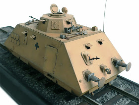
Here are some more images of Dragon Models 1/35 scale s.Sp.Artilleriewagen. The s.Sp.Artilleriewagen was an armored rail car designed to protect cargo trains.