Translate

Friday, April 6, 2012

M1070 Truck Tractor & M1000 Heavy Equipment Transporter Semi-Trailer With M1 Abrams Panther II


Here are some images of Hobby Boss's 1/35 scale Oshkosh M1070 Truck Tractor & M1000 Heavy Equipment Transporter Semi-Trailer with Trumpeter's 1/35 scale M1 Abrams Panther II command vehicle.

From Wikipedia"

In 1993 the U.S. Army started fielding the M1070 Truck Tractor and the M1000 Heavy Equipment Transporter Semi-trailer. The tractor is produced by Oshkosh Truck, and the trailer is manufactured by Systems & Electronics, Inc. in St. Louis. The HET transports payloads up to 70 tons – primarily Abrams tanks, but is also used for other large military equipment such as forklifts and various tracked vehicles. It is capable of operating on highways (with permits), secondary roads, and cross-country. This version of the HET has a number of features that significantly improve the mobility and overall performance of the system in a tactical environment. The M1070 tractor has front- and rear-axle steering, a central tire-inflation system, and cab space for six personnel to accommodate the two HET operators and four tank crewmen. The M1000 semi-trailer has automatically steerable axles and a load-leveling hydraulic suspension. It is air-transportable by both C-5 Galaxy and C-17 Globemaster III aircraft.

The Oshkosh 1070F (8×8) heavy equipment transporter (HET) became the new British Army heavy tank transporter in 2001 replacing the Scammell Commander. The Oshkosh Corporation have supplied over 2,600 Heavy Equipment Transporters to the US Army in various engine configurations such as the 1070E and the 1070E1. The UK version (1070F) is compliant to European legislation on emissions (EURO III).

Tuesday, April 3, 2012

M1070 Truck Tractor


Here are some images of Hobby Boss's 1/35 scale Oshkosh M1070 Truck Tractor.

From Wikipedia"


M1070 tractor
Length: 30 feet 2 inches (9.19 m)
Width: 8 feet 6 inches (2.59 m)
Height: 12 feet 1 inch (3.68 m)
Weight: 41,000 pounds (19,000 kg)
Speed: 40-45 mph
Fuel: 150 Gallons in the driver-side tank, 100 Gallons in the passenger-side tank
Range: 300 miles
Crew: 2+4
Payload: 140,000 pounds (64,000 kg)
Engine: 500 horsepower Detroit Diesel 8V92 N/A
Transmission: Allison CLT-755 5-speed automatic with TC-496 torque converter
Fording: 28 in

Friday, March 30, 2012

M1 Abrams Panther II


Here are some images of Trumpeter Models 1/35 scale M1 Abrams Panther II mine clearing vehicle.

From Global Security .org"

The M1 Abrams Panther II is an M1 Abrams Main Battle Tank specially modified for mine clearing missions. Modifications include the removal the turret, and installation of mine rollers on the front of the vehicle and Omnitech's Standardized Teleoperation System.

The Panther II is a 43-ton, remote controlled vehicle that can clear a 50,000-square-foot minefield in one hour. It can be operated up to 2,600 feet away. The M1 Abrams Panther is an M1 Abrams Main Battle Tank specially modified for mine clearing missions. Modifications to the Abrams tank include the removal the turret, and installation of mine rollers on the front of the vehicle. Rollers attached to the front of the vehicle explode landmines without causing damage to the vehicle. Weighing 43 tons, the Panther II can clear a 5,000-square-meter area within an hour. Plow and roller kit attachments push mines out of the way when clearing roads without damaging the vehicle.

The remote-controlled Panther II mine-clearing vehicle allows engineers to increase safety and efficiency standards. The Panther II offers a marked improvement over current methods of clearing mines and unexploded ordnance from roads and assembly areas during contingency operations. Instead of putting sappers (engineers) on the ground with mine detectors and probes, the vehicle can rapidly and thoroughly clear large, hazardous areas at an extremely low risk to soldiers and civilians.

It is not difficult to use. Soldiers can operate the Panther II from 2,600 feet away, but generally keep it at about 800 meters. It's not like a remote-controlled plastic car where if you run into a building it's no big deal. With this vehicle there would be some serious damage done. If needed, a panic button located in the briefcase-sized remote control can halt the vehicle immediately. The vehicle can clear lanes effectively and efficiently, saving man hours, and it will save engineer lives by demolishing mines.

Wednesday, March 28, 2012

Piper Super Cub Composite


Here is my composite image of Revell's 1/32 scale Piper Super Cub against a cloudy blue sky with none other than Graphic Pen Len at the controls .

Images of the model can be seen here.

Tuesday, March 27, 2012

Monday, March 26, 2012

Sunday, March 25, 2012

Consolidated PBY-5 Catalina Composite


Here is my composite image of Monograms 1/48 scale Consolidated PBY-5 Catalina reconnaissance and rescue aircraft against a cloudy sky.

Images of the model can be seen here.

Saturday, March 24, 2012

Grumman F4F-3 Wildcat


Here are some better images of Trumpeter's 1/32 scale 1/32 scale Grumman F4F-3 Wildcat in pre war markings.

From Wikipedia"

US Navy orders followed as did some (with Wright Cyclone engines) from France; these ended up with the Royal Navy's Fleet Air Arm after the fall of France and entered service on 8 September 1940. These aircraft, designated by Grumman as G-36A, had a different cowling from other earlier F4Fs and fixed wings, and were intended to be fitted with French armament and avionics following delivery. In British service initially, the aircraft were known as the Martlet I, but not all Martlets would be to exactly the same specifications as US Navy aircraft. All Martlet Is featured the four .50 in (12.7 mm) M2 Browning machine guns of the F4F-3 with 450 rpg. The British directly ordered and received a version with the original Twin Wasp, but again with a modified cowling, under the manufacturer designation G-36B. These aircraft were given the designation Martlet II by the British. The first 10 G-36Bs were fitted with non-folding wings and were given the designation Martlet III. These were followed by 30 folding wing aircraft (F4F-3As) which were originally destined for the Hellenic Air Force, which were also designated Martlet IIIs. On paper, the designation changed to Marlet III(A) when the second series of Martlet III was introduced.

Poor design of the armament installation on early F4Fs caused these otherwise reliable machine guns to frequently jam, a problem common to wing-mounted weapons of many US fighters early in the war. It was an F4F-3 flown by Lieutenant Edward O'Hare that in a few minutes shot down five Mitsubishi twin-engine bombers attacking Lexington off Bougainville on 20 February 1942. But contrasting with O'Hare's performance, his wingman was unable to participate because his guns would not function.

A shortage of two-stage superchargers lead to the development of the F4F-3A, which was basically the F4F-3 but with a 1,200 hp (890 kW) Pratt & Whitney R-1830-90 radial engine with a more primitive single-stage two-speed supercharger. The F4F-3A, which was capable of 312 mph (502 km/h) at 16,000 ft (4,900 m), was used side by side with the F4F-3, but its poorer performance made it unpopular with US Navy fighter pilots. The F4F-3A would enter service as the Martlet III(B).

At the time of Pearl Harbor, only Enterprise had a fully equipped Wildcat squadron, VF-6 with F4F-3As. Enterprise was then transferring a detachment of VMF-211, also equipped with F4F-3s, to Wake. Saratoga was in San Diego, working up for operations of the F4F-3s of VF-3. 11 F4F-3s of VMF-211 were at the Ewa Marine Air Corps Station on Oahu; nine of these were damaged or destroyed during the Japanese attack. The detachment of VMF-211 on Wake lost seven Wildcats to Japanese attacks on 8 December, but the remaining five put up a fierce defense, making the first bomber kill on 9 December. The destroyer Kisaragi was sunk by the Wildcats, and the Japanese invasion force retreated.

In May 1942, the F4F-3s of VF-2 and VF-42, onboard Yorktown and Lexington, participated in the Battle of the Coral Sea. Lexington and Yorktown fought against the Zuikaku, Shōkaku and the light carrier Shōhō in this battle, in an attempt to halt a Japanese invasion of Port Moresby on Papua. During these battles, it became clear that attacks without fighter escort amounted to suicide, but that the fighter component on the carriers was completely insufficient to provide both fighter cover for the carrier and an escort for an attack force. Most US carriers carried less than 20 fighters.

Friday, March 23, 2012

Supermarine Spitfire MK 1


Here are some better images of M.P.Cs (Airfix molds) 1/24 scale Supermarine Spitfire MK 1.

From Wikipedia"

The British Supermarine Spitfire was the only fighter aircraft of the Second World War to fight in front line service, from the beginnings of the conflict, in September 1939, through to the end in August 1945. Post-war the Spitfire's service career continued into the 1950s. The basic airframe proved to be extremely adaptable, capable of taking far more powerful engines and far greater loads than its original role as a short-range interceptor had allowed for. This would lead to 19 marks of Spitfire and 52 sub-variants being produced throughout the Second World War and beyond. The many changes were made in order to fulfil Royal Air Force requirements and to successfully combat ever-improving enemy aircraft. With the death of Reginald J. Mitchell in June 1937, all variants of the Spitfire were designed by his replacement, Joseph Smith, and a team of engineers and draftsmen.

These articles present a brief history of the Spitfire through all of its variants, including many of the defining characteristics of each sub-type. This article deals with Spitfires powered by early Rolls-Royce Merlin engines which mostly utilised single-speed, single-stage superchargers. The second article describes Spitfire variants powered by later Merlins, with two-stage, two-speed superchargers, while the final article describes the Spitfires powered by Rolls-Royce Griffon engines.


Thursday, March 22, 2012

Focke Wulf FW 190 A-5


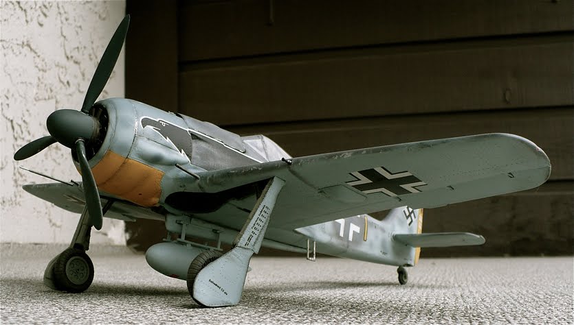
Here are some better images of Airfix's 1/24 scale Focke Wulf FW 190 A-5.

From Wikipedia"

The A-5 was developed after it was determined that the Fw 190 could easily carry more ordnance. The D-2 engine was moved forward another 15 cm (6 in), moving the center of gravity forward to allow more weight to be carried aft. Some A-5s were tested with the MW 50 installation: this was a mix of 50% methyl alcohol and 50% water, which could be injected into the engine to produce a short-term power boost to 2,000 PS (1,973 hp, 1,471 kW), but this system was not adopted for serial production. New radio gear, including FuG 25a Erstling IFF, and an electric artificial horizon found their way into the A-5. The A-5 retained the same basic armament as the A-4.

The A-5 too, saw several Umrüst-Bausätze kits. The U2 was designed as a night Jabo-Rei and featured anti-reflective fittings and exhaust flame dampeners. A centre-line ETC 501 rack typically held a 250 kg (550 lb) bomb, and wing-mounted racks mounted 300 L drop tanks. A EK16 gun camera, as well as landing lights, were fitted to the wing leading edge. The U2 was armed with only two 20 mm MG 151 cannon. The U3 was a Jabo fighter fitted with ETC 501s for drop tanks and bombs; it too featured only two MG 151s for armament. The U4 was a "recon" fighter with two RB 12.5 cameras and all armament of the basic A-5 with the exception of the MG FF cannon. The A-5/U8 was another Jabo-Rei outfitted with SC-250 centreline-mounted bombs, under-wing 300-litre drop tanks and only two MG 151s; it later became the Fw 190 G-2. A special U12 was created for bomber attack, outfitted with the standard 7.92 mm (.312 in) MG 17 and 20 mm MG 151 but replacing the outer wing 20 mm MG-FF cannon with two underwing gun pods containing two 20 mm MG 151/20 each, for a total of two machine guns and six cannon. The A-5/U12 was the prototype installation of what was known as the R1 package from the A-6 onwards. The A-5/R11 was a night fighter conversion fitted with FuG 217 Neptun (Neptune) radar equipment with arrays of three dipole antenna elements vertically mounted fore and aft of the cockpit and above and below the wings. Flame-dampening boxes were fitted over the exhaust exits. 1,752 A-5s were built from November 1942 to June 1943.

Monday, March 19, 2012

1910 Ford Model T


Here are some images of Lindberg models 1/16 scale 1910 Ford Model T.
I know what you're thinking. There is no such thing as a white 1910 Ford Model T. The fact is I wanted to see what a white one would look like, and I must say it looks pretty good.

From Wikipedia"

By 1918, half of all the cars in the US were Model T’s. However it was a monolithic bloc; Ford wrote in his autobiography that he told his management team in 1909 that in the future “Any customer can have a car painted any color that he wants so long as it is black”.

However, in the first years of production from 1908 to 1914, the Model T was not available in black but rather only grey, green, blue, and red. Green was available for the touring cars, town cars, coupes, and Landaulets. Grey was only available for the town cars, and red only for the touring cars. By 1912, all cars were being painted midnight blue with black fenders. It was only in 1914 that the "any color as long as it is black" policy was finally implemented. It is often stated that Ford suggested the use of black from 1914 to 1926 due to the cheap cost and durability of black paint. During the lifetime production of the Model T, over 30 different types of black paint were used on various parts of the car. These were formulated to satisfy the different means of applying the paint to the various parts, and had distinct drying times, depending on the part, paint, and method of drying.

Sunday, March 18, 2012

ISS Extravehicular Mobility Unit (EMU)


Here are some images of Bandai's 1/10 scale ISS Extravehicular Mobility Unit (EMU).
Being the patriotic Canadian that I am I decided to base this suit off of one of the ones worn by astronaut/physician Dafydd Rhys Williams on STS mission 118. With the addition of little glasses I tried to kinda sorta to make it in a indirect way to look like him. Kinda :-/
This kit is the usual Bandai high quality and a great addition to any space model collection, and yes it even comes with a lighting pack.
My only complaints are that for an expensive model it only took a day to build. Plus they failed to supply a waste belt which is clearly a part of the space suit. They do show it on the box top but as to why it wasn't supplied is anyone's guess. I will have to scratch one in the future when I get some proper material to work with.

From Wikipedia"
The Space Shuttle/International Space Station Extravehicular Mobility Unit (EMU) is an independent anthropomorphic system that provides environmental protection, mobility, life support, and communications for a Space Shuttle or International Space Station (ISS) crew member to perform extra-vehicular activity (EVA) in earth orbit. Introduced in 1982, it is a two-piece semi-rigid suit, and is currently one of two spacesuits used by crew members on the ISS, the other being the Russian Orlan space suit.

The EMU, like the Apollo/Skylab A7L spacesuit, was the result of years of research and development. It consists of a Hard Upper Torso (HUT) assembly, a Primary Life Support System (PLSS) which incorporates the life support and electrical systems, arm sections, gloves, an Apollo-style "bubble" helmet, the Extravehicular Visor Assembly (EVVA), and a soft Lower Torso Assembly (LTA), incorporating the Body Seal Closure (BSC), waist bearing, brief, legs, and boots. Prior to donning the pressure garment, the crew member puts on a Maximum Absorbency Garment (MAG) (basically a modified incontinence diaper – Urine Collection Devices (UCDs) are no longer used), and possibly a Thermal Control Undergarment (long johns). The final item donned before putting on the pressure suit is the "Liquid Cooling and Ventilation Garment" (LCVG), which incorporates clear plastic tubing through which chilled liquid water flows for body temperature control, as well as ventilation tubes for waste gas removal.

After donning the LCVG, the astronaut then puts on the LTA, before entering the airlock. The astronaut then dons the HUT, connects the LCVG umbilical to the umbilical in the HUT, and then locks the two parts of the suit together using the Body Seal Closure. Once the suit is turned on and checked out, the astronaut dons a "Snoopy cap," a brown and white fabric communications cap dating back to the Apollo days, which incorporates a pair of earphones and microphones, allowing the EVA astronaut to communicate with both the crew members in the orbiter and ground controllers in Houston. After donning the "Snoopy cap," the gloves and helmet are then locked on, pressurizing the suit. The suit's regulator and fans activate when the servicing umbilicals are removed and the suit reaches an internal pressure of 4.3 psi (30 kPa). A typical EMU can support an astronaut for 8.5 hours, with 30 minutes of reserves in the case of primary life support failure. To perform an EVA from the shuttle, the cabin pressure is reduced from 14.7 psi to 10.2 psi for 24 hours, after which an astronaut must pre-breathe for 45 minutes. For EVAs onboard the ISS, the astronaut must pre-breathe for about four hours.

The EMU hardware and accessories (PLSS, helmet, communications cap, and locking rings for the helmet and gloves), is manufactured by the Hamilton Sundstrand division of United Technologies out of Windsor Locks, Connecticut, while the suit's soft components (the arms of the HUT and the entire LTU) are produced by ILC Dover out of Frederica, Delaware. The two companies, who were rivals during the early days of Apollo for the contract to build the "Block II" (moonwalking) space suit, teamed up in 1974 against the David Clark Company and Garrett AiResearch for the EMU development and construction. During Apollo, the ILC Dover-produced A7L used the life support backpack, helmet, and locking rings supplied by Hamilton United, but originally, ILC Dover was to just supply the arms and legs of the suit, a similar process that is still going on today.

Dafydd Rhys "Dave" Williams (born May 16, 1954) is a Canadian physician and a retired CSA astronaut. He had two spaceflights, both of which were Space Shuttle missions. His first spaceflight, STS-90 in 1998, was a 16-day mission aboard Space Shuttle Columbia dedicated to neuroscience research. His second flight, STS-118 in August 2007, was flown by Space Shuttle Endeavour to the International Space Station. During that mission he performed three spacewalks, becoming the second Canadian to perform a spacewalk and setting a Canadian record for total number of spacewalks. These spacewalks combined for a total duration of 17 hours and 47 minutes.

In 1998, Williams became the first non-American to hold a senior management position within NASA, when he held the position of Director of the Space and Life Sciences Directorate at the Johnson Space Center.

STS-118

Williams was assigned to the crew of STS-118 (August 8 to 21, 2007), an assembly mission to the International Space Station. He completed three spacewalks during this mission, and set two new records during his final EVA on Saturday, 18 August: he is the Canadian with the most spacewalks (3); and he passed Canadian Astronaut Chris Hadfield in total EVA time. Williams ended Saturday's EVA with a total of 17 hours, 47 minutes of extravehicular time. He was the second Canadian to lead an EVA, after Chris Hadfield, who led an EVA during STS-100.


Friday, March 16, 2012

U-Boot Typ 212 A


Here are some images of Revell's 1/144 scale type 212 A U Boat.
What can I say but this model was fun to build. Not much to it but a nice result in the end.

From Wikipedia"
The German Type 212 class, also Italian Todaro class, is a highly advanced design of non-nuclear submarine (U-boat) developed by Howaldtswerke-Deutsche Werft AG (HDW) and Fincantieri S.p.a. for the German and Italian Navy. It features diesel propulsion and an additional air-independent propulsion (AIP) system using Siemens proton exchange membrane (PEM) hydrogen fuel cells. The submarine can operate at high speed on diesel power or switch to the AIP system for silent slow cruising, staying submerged for up to three weeks without surfacing and with no exhaust heat. The system is also said to be vibration-free, extremely quiet and virtually undetectable.
Type 212 is the first of the only two fuel cell propulsion system equipped submarines ready for series production by 2007, the other being the Project 677 Lada class submarine designed by Russian Rubin Design Bureau.
At the beginning of the 1990s the German Navy was seeking a replacement for the Type 206 submarines. Initial study started on a Type 209 improved design, with AIP capability, called Type 212.
The final programme started in 1994 as the two navies of Germany and Italy began working together to design a new conventional submarine, respectively to operate in the shallow and confined waters of the Baltic sea and in the deeper waters of the Mediterranean sea. The two different requirements were mixed into a common one and, because of significant updates to the design, the designation was changed to Type 212A since then.
In 1996 a Memorandum of Understanding (MOU) gave the start to the cooperation. Its main aim was the construction of identical boats and the start of a collaboration in logistic and life-cycle support for the two navies.
The German government placed an initial order of four Type 212A submarines in 1998. The German Submarine Consortium built them at the shipyards of HDW and Thyssen Nordseewerke GmbH (TNSW) of Emden. Different sections of the submarines were constructed at both sites at the same time and then half of them were shipped to the respective other yard so that both HDW and Thyssen Nordseewerke assembled two complete submarines each.
In the same year the Italian government placed an order of two U212A submarines built by Fincantieri for the Marina Militare (Italian Navy) at Muggiano shipyard, designated as the Todaro class.
The German Navy ordered two additional, improved submarines in 2006, to be delivered from 2012 on. They will be 1.2 meters longer to give additional space for a new reconnaissance mast.
On 21 April 2008 the Italian Navy ordered a second batch of submarine in the same configuration of the original ones. Some upgrading should involve materials and components of commercial derivation, as well as the software package of the CMS. The intention is to keep the same configuration of the first series and reduce maintenance costs.
The export-oriented Type 214 submarine succeeds the Type 209 submarine and shares certain features with the Type 212A, such as the AIP fuel cell propulsion.
Partly owing to the "X" arrangement of the stern planes, the Type 212 is capable of operating in as little as 17 metres of water, allowing it to come much closer to shore than most contemporary submarines. This gives it an advantage in covert operations, as SCUBA-equipped commandos operating from the boat can surface close to the beach and execute their mission more quickly and with less effort.
A notable design feature is the prismatic hull cross-section and smoothly faired transitions from the hull to the sail, improving the boat's stealth characteristics. The ship and internal fixtures are constructed of nonmagnetic materials, significantly reducing the chances of it being detected by magnetometers or setting off magnetic naval mines.
The low emission profile allowed the submarines in exercises to intrude even into well protected opposing forces such as carrier formations with their screen.
Although hydrogen–oxygen propulsion had been considered for submarines as early as World War I, the concept was not very successful until recently due to fire and explosion concerns. In the Type 212 this has been countered by storing the fuel and oxidizer in tanks outside the crew space, between the pressure hull and outer light hull. The gases are piped through the pressure hull to the fuel cells as needed to generate electricity, but at any given time there is only a very small amount of gas present in the crew space.
Currently, the Type 212A is capable of launching the fiber optic-guided DM2A4 Seehecht ("Seahake") heavyweight torpedoes, the WASS A184 Mod.3 torpedoes, the WASS BlackShark torpedoes and short-range missiles from its six torpedo tubes, which use a water ram expulsion system. Future capability may include tube-launched cruise missiles.
The short-range missile IDAS (based on the IRIS-T missile), primarily intended for use against air threats as well as small or medium-sized sea- or near land targets, is currently being developed by Diehl BGT Defence to be fired from Type 212's torpedo tubes. IDAS is fiber-optic guided and has a range of approx. 20 km. Four missiles fit in one torpedo tube, stored in a magazine. First deliveries of IDAS for the German Navy are scheduled from 2014 on.
A 30 mm auto-cannon called Muräne (moray) to support diver operations or to give warning shots is being considered too. The cannon, probably a version of the RMK30 built by Rheinmetall, will be stored in a retractable mast and can be fired without the boat emerging. The mast will also be designed to contain three Aladin UAVs for reconnaissance missions. This mast is likely to be mounted on the 2nd batch of Type 212 submarines for the German Navy.

Hawker Class Composite


Here is my composite image of my kit bash model of the Hawker class starship the U.S.S. Gambit cruising past the Neptune moon Triton.

Images of the model can be seen here.