Translate

Saturday, November 30, 2013

Messerschmitt Bf 110 C-7 - 2

Here are some more images of Dragon Models 1/32 scale Messerschmitt Bf 110 C-7 fighter bomber.

From Wikipedia"
The Messerschmitt Bf 110, often (erroneously) called Me 110, was a twin-engine heavy fighter (Zerstörer - German for "Destroyer") in the service of the Luftwaffe during World War II. Hermann Göring was a proponent of the Bf 110, and nicknamed it his Eisenseiten ("Ironsides"). Development work on an improved type to replace the Bf 110, the Messerschmitt Me 210 began before the war started, but its teething troubles resulted in the Bf 110 soldiering on until the end of the war in various roles, alongside its replacements, the Me 210 and the Me 410.
The Bf 110 served with success in the early campaigns, the Polish, Norwegian and Battle of France. The Bf 110's lack of agility in the air was its primary weakness. This flaw was exposed during the Battle of Britain, when some Bf 110-equipped units were withdrawn from the battle after very heavy losses and redeployed as night fighters, a role to which the aircraft was well suited. The Bf 110 enjoyed a successful period following the Battle of Britain as an air superiority fighter and strike aircraft in other theatres. During the Balkans Campaign, North African Campaign and on the Eastern Front, it rendered valuable ground support to the German Army as a potent fighter-bomber (Jagdbomber or Jabo). Later in the war, it was developed into a formidable night fighter, becoming the major night-fighting aircraft of the Luftwaffe. Most of the German night fighter aces flew the Bf 110 at some point during their combat careers, and the top night fighter ace of all time, Major Heinz-Wolfgang Schnaufer, flew it exclusively and claimed 121 victories in 164 combat missions.

Genesis and competition Throughout the 1930s, the air forces of the major military powers were engaged in a transition from biplane to monoplane designs. Most concentrated on the single-engine fighter aircraft. But the problem of range arose. The Reichsluftfahrtministerium (RLM), pushed by Hermann Göring, issued a request for a new multipurpose fighter called the Kampfzerstörer (battle destroyer) with long range and an internal bombload. The request called for a twin-engine, three-seat, all-metal monoplane that was armed with cannon as well as a bomb bay. Only Bayerische Flugzeugwerke (Messerschmitt), Focke-Wulf and Henschel responded of the original seven companies.

Messerschmitt defeated Focke-Wulf, Henschel and Arado, and was given the funds to build several prototype aircraft. The Focke-Wulf design, the Focke-Wulf Fw 57, had a wing span of some 25.6 m (84 ft) and was powered by two DB 600 engines. It was armed with two 20 mm MG FF cannons in the nose and a third was positioned in a dorsal turret. The Fw 57 V1 flew in 1936 but its performance was poor and the machine crashed.The Henschel Hs 124 was similar in construction layout to the Fw 57. Equipped with two Jumo 210C for the V1. The V2 utilized the BMW 132Dc radial engines generating 870 PS compared with the 640 PS Jumo. The armaments consisted of a single rearward-firing 7.92 mm (.312 in) MG 15 machine gun and a single forward-firing 20 mm MG FF cannon.
Messerschmitt omitted the internal bomb load requirement from the RLM directive to increase the armament element of the RLM specification. The Bf 110 was far superior to its rivals in providing the speed, range and firepower to meet its role requirements. By the end of 1935, the Bf 110 had evolved into an all-metal, low-wing cantilever monoplane of semi-monocoque design featuring twin rudders and powered by two DB 600A engines. The design was also fitted with Handley-Page wing slots.
Early variants
By luck (and pressure by Ernst Udet), RLM reconsidered the ideas of the Kampfzerstörer and began focussing on the Zerstörer. Due to these changes, the Bayerische Flugzeugwerke design better fitted RLM's requests. On 12 May 1936, Rudolf Opitz flew the first Bf 110 out of Augsburg. But, as many pre-war designs found, the engine technologies promised were not up to acceptable reliability standards. Even with the temperamental DB 600 engines, the RLM found the Bf 110, while not as maneuverable as desired, was quite a bit faster than its original request specified, as well as faster than the then-current front line fighter, the Bf 109 B-1. Thus the order for four pre-production A-0 units was placed. The first of these were delivered on January 1937. During this testing, both the Focke-Wulf Fw 187 and Henschel Hs 124 competitors were rejected and the Bf 110 was ordered into full production.
The initial deliveries of the Bf 110 encountered several issues with delivery of the DB 600 motors, which forced Bayerische Flugzeugwerke to install Junkers Jumo 210B engines, leaving the Bf 110 seriously underpowered and able to reach a top speed of only 431 km/h (268 mph). The armament of the A-0 units was also limited to four nose-mounted 7.92 mm (.312 in) MG 17 machine guns.
Even without delivery of the DB 600 engines, Bayerische Flugzeugwerke began assembly of the Bf 110 in the summer of 1937. As the DB 600 engines continued to have issues, Bayerische Flugzeugwerke was forced to keep on using Jumo motors, the 210G, which supplied 515 kW (700 PS) each (versus the 471 kW/640 PS supplied by the 210B). Three distinct versions of the Bf 110B were built, the B-1, which featured four 7.92 mm (.312 in) MG 17 machine guns and two 20 mm MG FF cannons. The B-2 reconnaissance version, which had a camera in place of the cannons, and the B-3 which was used as a trainer, with the cannons replaced by extra radio equipment. Only 45 Bf 110Bs were built before the Jumo 210G engine production line ended. The major identifier of the A and B 110s was the very large "mouth" bath radiators located under the engine.
In late 1938, the DB 601 B-1 engines finally became available. With the new engine, the design teams removed the radiators under the engine and replaced them with water/glycol radiators, placing them under the wing to the outside of the engines. With the DB 601 engine, the Bf 110's maximum speed increased to a respectable 541 km/h (336 mph) with a range of approximately 1,094 km (680 mi).
Bf 110 C-7
Fighter-bomber based on C-4/B, two ETC-500 centerline bomb racks capable of carrying two 500 kg (1,100 lb) bombs, uprated DB 601P engines.

M16A1 Rifle And M16A2/M203 With Grenade Launcher


Here are a couple of images of Trumpeter's 1/3 scale AR15/M16/M4 Family M16A2/M203 Rifle with Grenade Launcher and Trumpeter's 1/3 scale AR15/Mi6/M4 Family M16A1 Rifle.

From Wikipedia"
The M16 (more formally Rifle, Caliber 5.56 mm, M16) is the United States military designation for the AR-15 rifle. Colt purchased the rights to the AR-15 from ArmaLite and currently uses that designation only for semi-automatic versions of the rifle. The M16 rifle fires the 5.56x45mm cartridge and can produce massive wounding effects when the bullet impacts at high velocity and yaws in tissue leading to fragmentation and rapid transfer of energy.
The M16 entered United States Army service and was deployed for jungle warfare operations in South Vietnam in 1963, becoming the standard U.S. rifle of the Vietnam War by 1969, replacing the M14 rifle in that role. The U.S. Army retained the M14 in CONUS, Europe, and South Korea until 1970. Since the Vietnam War, the M16 rifle family has been the primary infantry rifle of the U.S. military. With its variants (M16A1, M16A2, M16A3, and M16A4), it has been used by almost a hundred countries. Total worldwide production of M16-style weapons since the design's inception has been approximately 8 million, making it the most produced firearm in its caliber. The M16 is being phased out in the United States Army and is being replaced by the M4 carbine series as of 2010.

XM16E1 and M16A1 (Colt Model 603)

The U.S. Army XM16E1 was essentially the same weapon as the M16 with the addition of a forward assist and corresponding notches in the bolt carrier. The M16A1 was the finalized production model in 1967. To address issues raised by the XM16E1's testing cycle, a closed, bird-cage flash suppressor replaced the XM16E1's three-pronged flash suppressor which caught on twigs and leaves. Various other changes were made after numerous problems in the field. Cleaning kits were developed and issued while barrels with chrome-plated chambers and later fully-lined bores were introduced.
With these and other changes, the malfunction rate slowly declined and new soldiers were generally unfamiliar with early problems. A rib was built into the side of the receiver on the XM16E1 to help prevent accidentally pressing the magazine release button while closing the ejection port cover. This rib was later extended on production M16A1s to help in preventing the magazine release from inadvertently being pressed. The hole in the bolt that accepts the cam pin was crimped inward on one side, in such a way that the cam pin may not be inserted with the bolt installed backwards, which would cause failures to eject until corrected. The M16A1 remains in service in limited numbers in the United States but is still standard issue in many world armies.


The development of the M16A2 rifle was originally requested by the United States Marine Corps as a result of the USMC's combat experience in Vietnam with the XM16E1 and M16A1. The Marines were the first branch of the U.S. Armed Forces to adopt the M16A2 in the early/mid 1980s with the United States Army following suit in the late 1980s. This rifle is now the current issue to Marine Corps' recruits in both MCRD San Diego and MCRD Parris Island. Modifications to the M16A2 were extensive. In addition to the new rifling, the barrel was made with a greater thickness in front of the front sight post to resist bending in the field and to allow a longer period of sustained fire without overheating. The rest of the barrel was maintained at the original thickness to enable the M203 grenade launcher to be attached. The front sight was now a square post with 4 detent positions, adjustable for vertical zeroing by using a cartridge, nail or special tool. A new adjustable rear sight was added, allowing the rear sight to be dialed in for specific range settings between 300 and 800 meters to take full advantage of the ballistic characteristics of the new SS109 rounds and to allow windage adjustments without the need of a tool or cartridge. The flash suppressor was again modified, this time to be closed on the bottom so it would not kick up dirt or snow when being fired from the prone position, and acting as a recoil compensator. The front grip was modified from the original triangular shape to a round one, which better fitted smaller hands and could be fitted to older models of the M16. The new handguards were also symmetrical so that armories need not separate left and right spares. The handguard retention ring was tapered to make it easier to install and uninstall the handguards. A notch for the middle finger was added to the pistol grip, as well as more texture to enhance the grip. The buttstock was lengthened by 5/8 inch (16 mm). The new buttstock became ten times stronger than the original due to advances in polymer technology since the early 1960s. Original M16 stocks were made from fiberglass-impregnated resin; the newer stocks were engineered from DuPont Zytel glass-filled thermoset polymers. The new stock included a fully textured polymer buttplate for better grip on the shoulder, and retained a panel for accessing a small compartment inside the stock, often used for storing a basic cleaning kit. The heavier bullet reduces muzzle velocity from 3,200 feet per second (980 m/s), to about 3,050 feet per second (930 m/s). The A2 also uses a faster twist rifling to allow the use of a trajectory-matched tracer round. A spent case deflector was incorporated into the upper receiver immediately behind the ejection port to prevent cases from striking left-handed users.

The action was also modified, replacing the fully-automatic setting with a three-round burst setting. When using a fully-automatic weapon, poorly trained troops often hold down the trigger and "spray" when under fire. The U.S. Army concluded that three-shot groups provide an optimum combination of ammunition conservation, accuracy and firepower. There are mechanical flaws in the M16A2 burst mechanism. The trigger group does not reset when the trigger is released. If the user releases the trigger between the second and third round of the burst, for example, the next trigger pull would only result in a single shot. Even in semi-automatic mode, the trigger group mechanism affects weapon handling. With each round fired, the trigger group cycles through one of the three stages of the burst mechanism. Worse, the trigger pull at each of these stages may vary as much as 6 lbf (27 N) in pressure differential, detracting from accuracy.

All together, the M16A2's new features added weight and complexity to the M16 series. Critics also point out that neither of the rear sight apertures is ideally sized. The smaller aperture was described as being too small, making quick acquisition of the front sight post difficult; and the larger aperture was described as being too large, resulting in decreased accuracy. To make matters worse, the rear sight apertures are not machined to be on the same plane. In other words, the point of impact changes when the user changes from one aperture to the other. The rear sight's range adjustment feature is rarely used in combat as soldiers tend to leave the rear sight on its lowest range setting of 300 meters. This distance is seen by many as an excessively long range for the minimum setting, given that most engagements take place at significantly shorter ranges. Despite criticism, a new rifle was needed both to comply with NATO standardization of the SS109 (M855) and to replace aging Vietnam era weapons in the inventory.
The M203 is a single shot 40 mm grenade launcher designed to attach to a rifle. It uses the same rounds as the older M79 "shotgun"-type grenade launcher, which utilize High-Low Propulsion System to keep recoil forces low. Though versatile, and compatible with many rifle models, the M203 was originally designed for the U.S. M16 and its variant, the M4 Carbine. The launcher can also be mounted onto a C7, a Canadian version of the M16 that uses an optical scope instead of an iron sight, and requires the bottom handguard on the rifle to be removed in order to mount the launcher.

Stand-alone variants of the M203 exist, as do versions designed specifically for many other rifles. The device attaches under the barrel, the launcher trigger being in the rear of the launcher, just forward of the rifle magazine. The rifle magazine functions as a hand grip when firing the M203. A separate sighting system is added to rifles fitted with the M203, as the rifle's standard sights are not matched to the launcher. The version fitted to the Canadian C7 has a sight attached to the side of the launcher, either on the left or right depending on the user's needs.

Friday, November 29, 2013

HMS Illustrious (R06) - 2

Here are some more images of Airfix's 1/350 scale HMS Illustrious (R06).
The big complaint I have about this kit was the lack of detail this kit contained. Thankfully I had spare railing and netting kicking around to bring its detail level up. Though I won't attest to the accuracy. I did the best I could with the materials on hand.

From Wikipedia"

HMS Illustrious is the second of three Invincible-class light aircraft carriers built for the Royal Navy in the late 1970s and early 1980s. She is the fifth warship and second aircraft carrier to bear the name Illustrious, and is affectionately known as "Lusty" to her crew. The vessel just missed the Falklands Conflict, but was deployed to Iraq and Bosnia in the 1990s and to Sierra Leone in 2000. An extensive re-fit in 2002 meant that she missed the Iraq War, but she was finished in time to assist British citizens trapped by the 2006 Lebanon War.
Following the retirement of her fixed-wing Harrier II aircraft in 2010, Illustrious now operates as one of two Royal Navy helicopter carriers. She is the oldest ship in the active fleet and it is envisaged that she will be withdrawn from service in 2014 (after 32 years service) and will not be replaced until HMS Queen Elizabeth is commissioned later in the decade.
 Illustrious, the second of the planned three Invincible class aircraft carriers, was laid down at Swan Hunter on the River Tyne in 1976 and launched in 1978. As the ship neared the end of its fitting out period, the Falklands War broke out. As a consequence, work on Illustrious was greatly speeded up. The war was won before Illustrious could be finished, but she did perform a useful service in the aftermath. Until the RAF airfield on the Falkland Islands was repaired, an aircraft carrier was required on station to protect the area from possible Argentine attack. Invincible had been on station for many months when Illustrious arrived to its relief. Illustrious was needed so quickly that the ship was commissioned whilst underway. Rear Admiral Derek Reffell commanded the relief task group from Illustrious during this period. After the RAF airfield was repaired, Illustrious returned to the UK for a full shakedown cruise and workup period, with a formal commissioning on 20 March 1983.

Thursday, November 28, 2013

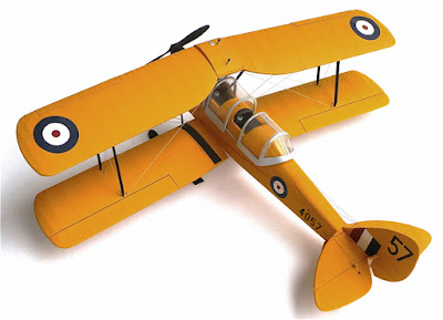
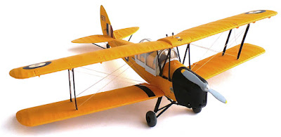
de Havilland DH. 82 C Tiger Moth With Skis

Here are some images of Revell's 1/32 scale de Havilland DH. 82 C Tiger Moth (Matchbox molds). This aircraft has the markings of 4057 No. 6 elementary flying training school, RCAF, Prince Albert Saskatchewan 1940. The Tiger Moth was one of the primary trainers during World War Two and was used as a trainer for the RAF until 1952 when they were released to the civilian market. Many flying examples of this aircraft can be seen to this day. This is one of the great Matchbox kits from the 1970s and thankfully is still available to this day. At around $30 Cdn this kit is a great buy.

From Wikipedia"

The de Havilland DH 82 Tiger Moth is a 1930s biplane designed by Geoffrey de Havilland and was operated by the Royal Air Force (RAF) and others as a primary trainer. The Tiger Moth remained in service with the RAF until replaced by the de Havilland Chipmunk in 1952, when many of the surplus aircraft entered civil operation. Many other nations used the Tiger Moth in both military and civil applications, and it remains in widespread use as a recreational aircraft in many countries. It is still occasionally used as a primary training aircraft, particularly for those pilots wanting to gain experience before moving on to other tailwheel aircraft, although most Tiger Moths have a skid. Many are now employed by various companies offering trial lesson experiences. Those in private hands generally fly far fewer hours and tend to be kept in concours condition. The de Havilland Moth club founded 1975 is now a highly organized owners' association offering technical support and focus for Moth enthusiasts.
The Tiger Moth trainer prototype was derived from the DH 60 de Havilland Gipsy Moth in response to Air Ministry specification 13/31 for an ab-initio training aircraft. The main change to the DH Moth series was necessitated by a desire to improve access to the front cockpit since the training requirement specified that the front seat occupant had to be able to escape easily, especially when wearing a parachute. Access to the front cockpit of the Moth predecessors was restricted by the proximity of the aircraft's fuel tank directly above the front cockpit and the rear cabane struts for the upper wing. The solution adopted was to shift the upper wing forward but sweep the wings back to maintain the centre of lift. Other changes included a strengthened structure, fold-down doors on both sides of the cockpit and a revised exhaust system. It was powered by a de Havilland Gipsy III 120 hp engine and first flew on 26 October 1931 with de Havilland Chief Test Pilot Hubert Broad at the controls.
One distinctive characteristic of the Tiger Moth design is its differential aileron control setup. The ailerons (on the lower wing only) on a Tiger Moth are operated by an externally mounted circular bellcrank, which lies flush with the lower wing's fabric undersurface covering. This circular bellcrank is rotated by metal cables and chains from the cockpit's control columns, and has the externally mounted aileron pushrod attached at a point 45° outboard and forward of the bellcrank's centre, when the ailerons are both at their neutral position. This results in an aileron control system operating, with barely any travel down at all on the wing on the outside of the turn, while the aileron on the inside travels a large amount upwards to counter-act adverse yaw.
From the outset, the Tiger Moth proved to be an ideal trainer, simple and cheap to own and maintain, although control movements required a positive and sure hand as there was a slowness to control inputs. Some instructors preferred these flight characteristics because of the effect of "weeding" out the inept student pilot.

Wednesday, November 27, 2013

Landing Craft Air Cushion (LCAC)

Here are some images of Trumpeter's 1/72 scale Landing Craft Air Cushion (LCAC).

From Wikipedia"

The Landing Craft Air Cushion (LCAC) is a class of air-cushion vehicle (hovercraft) used as landing craft by the United States Navy's Assault Craft Units and the Japan Maritime Self-Defense Force (JMSDF). They transport weapons systems, equipment, cargo and personnel of the assault elements of the Marine Air/Ground Task Force both from ship to shore and across the beach.
 Concept design of the present day LCAC began in the early 1970s with the full-scale Amphibious Assault Landing Craft (AALC) test vehicle. During the advanced development stage, two prototypes were built. JEFF A was designed and built by Aerojet General in California, with four rotating ducted propellers. JEFF B was designed and built by Bell Aerospace in New Orleans, Louisiana. JEFF B had two ducted rear propellers similar to the proposed SK-10 which was derived from the previous Bell SK-5 / SR.N5 hovercraft tested in Vietnam. These two craft confirmed the technical feasibility and operational capability that ultimately led to the production of LCAC. JEFF B was selected as the design basis for today’s LCAC.
The first 33 were included in the FY82-86 defense budgets, 15 in FY89, 12 each in FY90, FY91 and FY92, while seven were included in FY93. The first LCAC was delivered to the Navy in 1984 and Initial Operational Capability (IOC) was achieved in 1986. Approval for full production was granted in 1987. After an initial 15-craft competitive production contract was awarded to each of two companies, Textron Marine & Land Systems (TMLS) of New Orleans, La, and Avondale Gulfport Marine, TMLS was selected to build the remaining craft. A total of ninety-one LCAC have now been built. The final craft, LCAC 91, was delivered to the U.S. Navy in 2001. This craft served as the basis for the Navy’s LCAC Service Life Extension Program (SLEP).
Eight mine sweeping kits were acquired in 1994-1995. A Service Life Extension Program (SLEP) is currently in progress to add service life to the craft design life of 10 years, delaying the need to replace these versatile craft. 27 were to undergo the SLEP between 2000 and 2007. All 74 are to be completed by 2015. A number of LCACs are currently under development and testing at the Naval Support Activity Panama City in Panama City, Florida.
The craft operates with a crew of five. In addition to beach landing, LCAC provides personnel transport, evacuation support, lane breaching, mine countermeasure operations, and Marine and Special Warfare equipment delivery. The four main engines are all used for lift and all used for main propulsion. They are interchangeable for redundancy. A transport model can seat 180 fully equipped troops. Cargo capacity is 1,809 sq ft (168.1 m2). Bow ramp is 28.8 ft (8.8 m) while the stern ramp is 15 ft (4.6 m). Noise and dust levels are high with this craft. If disabled the craft is difficult to tow. In recent years spray suppression has been added to the craft's skirt to reduce interference with driver's vision.
According to the USMC the craft can cross 70% of the world's coastlines as opposed to about 15% for conventional landing craft, though the craft has more difficulty in rough seas than a conventional ship.
The US craft are shore based on each coast at Little Creek, Virginia and Camp Pendleton, California. A further ten are on reduced readiness, while two are assigned to research and development, and seven to support roles.
The LCAC will be replaced with the Ship-to-Shore Connector (SSC), a 73 short ton ACV, starting in 2019.
Six LCAC are in use by the Japan Maritime Self-Defense Force. Approval for the sale was given by the United States Government on 8 April 1994. The craft were built by Textron Marine & Land Systems in New Orleans, Louisiana. Purchase of the first craft was included in the FY93 budget, second in FY95, third in FY99 and fifth and sixth in FY00.


Tuesday, November 26, 2013

DH-82C Tiger Moth

Here are some more images of Matchbox 1/32 scale  de Havilland DH-82C Tiger Moth.
This friendly little devil served with the N0. 19 E.F.T.S Royal Canadian Air Force. Virden Manitoba in 1943.
From Wikipedia"

The de Havilland DH 82 Tiger Moth is a 1930s biplane designed by Geoffrey de Havilland and was operated by the Royal Air Force (RAF) and others as a primary trainer. The Tiger Moth remained in service with the RAF until replaced by the de Havilland Chipmunk in 1952, when many of the surplus aircraft entered civil operation. Many other nations used the Tiger Moth in both military and civil applications, and it remains in widespread use as a recreational aircraft in many countries. It is still occasionally used as a primary training aircraft, particularly for those pilots wanting to gain experience before moving on to other tailwheel aircraft, although most Tiger Moths have a skid. Many are now employed by various companies offering trial lesson experiences. Those in private hands generally fly far fewer hours and tend to be kept in concours condition. The de Havilland Moth club founded 1975 is now a highly organized owners' association offering technical support and focus for Moth enthusiasts.
The Tiger Moth trainer prototype was derived from the DH 60 de Havilland Gipsy Moth in response to Air Ministry specification 13/31 for an ab-initio training aircraft. The main change to the DH Moth series was necessitated by a desire to improve access to the front cockpit since the training requirement specified that the front seat occupant had to be able to escape easily, especially when wearing a parachute. Access to the front cockpit of the Moth predecessors was restricted by the proximity of the aircraft's fuel tank directly above the front cockpit and the rear cabane struts for the upper wing. The solution adopted was to shift the upper wing forward but sweep the wings back to maintain the centre of lift. Other changes included a strengthened structure, fold-down doors on both sides of the cockpit and a revised exhaust system. It was powered by a de Havilland Gipsy III 120 hp engine and first flew on 26 October 1931 with de Havilland Chief Test Pilot Hubert Broad at the controls.
One distinctive characteristic of the Tiger Moth design is its differential aileron control setup. The ailerons (on the lower wing only) on a Tiger Moth are operated by an externally mounted circular bellcrank, which lies flush with the lower wing's fabric undersurface covering. This circular bellcrank is rotated by metal cables and chains from the cockpit's control columns, and has the externally mounted aileron pushrod attached at a point 45° outboard and forward of the bellcrank's centre, when the ailerons are both at their neutral position. This results in an aileron control system operating, with barely any travel down at all on the wing on the outside of the turn, while the aileron on the inside travels a large amount upwards to counter-act adverse yaw.
From the outset, the Tiger Moth proved to be an ideal trainer, simple and cheap to own and maintain, although control movements required a positive and sure hand as there was a slowness to control inputs. Some instructors preferred these flight characteristics because of the effect of "weeding" out the inept student pilot.

Monday, November 25, 2013

Douglas SBD-5 Dauntless

Here are some images of Matchbox/Waldrons 1/32 scale Douglas SBD-5 Dauntless. From Wikipedia "
The Douglas SBD Dauntless was a naval dive bomber made by Douglas during World War II. The SBD was the United States Navy's main dive bomber from mid-1940 until late 1943, when it was largely replaced by the SB2C Helldiver. The aircraft was also operated by the United States Army as the A-24 Banshee.
The Northrop BT-1 provided the basis for the SBD, which began manufacture in 1940. Ed Heinemann led a team of designers who considered a development with a 1,000 hp (746 kW) Wright Cyclone powerplant. A year earlier, both the U.S. Navy and Marine Corps had placed orders for the new dive bombers, designated the SBD-1 and SBD-2 (the latter had increased fuel capacity and different armament). The SBD-1 went to the Marine Corps in late 1940, and the SBD-2 went to the Navy in early 1941.
The next version, designated SBD-3, began manufacture in early 1941. It provided increased protection, self-sealing fuel tanks, and four machine guns. The SBD-4 provided a 12 volt (from 6) electrical system, and a few were converted onto SBD-4P reconnaissance platforms.
The next (and most produced) variant, the SBD-5, was primarily produced at the Douglas plant at Tulsa, Oklahoma. It was equipped with a 1,200 hp (895 kW) engine and increased ammunition. Over 2,400 were built, and a few were shipped to the Royal Navy for evaluation. In addition to American service, the type saw combat against the Japanese with No. 25 Squadron of the Royal New Zealand Air Force, which soon replaced them with F4U Corsairs, and against the Germans with the Free French Air Force. A few were also sent to Mexico. The final version, the SBD-6, provided more improvements but production ended in summer 1944.
The U.S. Army had its own version of the SBD, known as the A-24 Banshee, which lacked the tail hook used for carrier landings, and a pneumatic tire replaced the solid tail wheel. First assigned to the 27th Bombardment Group (Light) at Hunter Field, Ga., A-24s participated in the Louisiana maneuvers during September 1941. There were three versions of the Banshee (A-24, the A-24A and A-24B) used by the Army in the early stages of the war. The USAAF used 948 of the 5,937 Dauntlesses built.
SBD-5
The most produced variant, primarily produced at the Douglas plant at Tulsa, Oklahoma. Equipped with a 1,200 hp (895 kW) engine and increased ammunition. 2,409 were built, and a few were shipped to the Royal Navy for evaluation. In addition to American service, the type saw combat against the Japanese with No. 25 Squadron of the Royal New Zealand Air Force which soon replaced them with F4U Corsairs, and against the Germans with the Free French Air Force. A few were also sent to Mexico

Sunday, November 24, 2013

Nakajima Ki-43 Oscar

Here are some more images of Hasegawa's 1/32 scale Nakajima Ki-43 Oscar with Manchukuo air corps markings. From Wikipedia "
The Nakajima Ki-43 Hayabusa (隼, "Peregrine Falcon") was a single-engine land-based tactical fighter used by the Imperial Japanese Army Air Force in World War II. The army designation was "Army Type 1 Fighter" (一式戦闘機); the Allied codename was "Oscar", but it was often called the "Army Zero" by American pilots for its resemblance to the Mitsubishi A6M Zero. Like the Japanese Navy's A6M Zero, the radial-engined Ki-43 was light and easy to fly. The Ki-43 was legendary for its combat performance in East Asia in the early years of the war.
It could outmaneuver any opponent, but did not have armor or self-sealing tanks. Its armament was poor until the last version in 1944. In spite of its drawbacks, the Ki-43 shot down more Allied aircraft than any other Japanese fighter and almost all the JAAF'S aces achieved most of their kills in it. Allied pilots often reported that the nimble Ki-43s were difficult targets, but burned easily or broke apart with few hits.
Total production amounted to 5,919 aircraft. Many of these were used during the last months of the war for kamikaze missions against the American fleet.
The Manchukuo Imperial Air Force (Chinese: 大満州帝国空軍 Dà Mǎnzhōu Dìguó Kōngjūn) was established in February 1937, initially with 30 men selected from the Manchukuo Imperial Army and trained at the Japanese Kwantung Army aircraft arsenal in Harbin. The official air force's predecessor was the Manchukuo Air Transport Company (later re-named the Manchukuo National Airways) a paramilitary airline formed in 1931, which undertook transport and reconnaissance missions for the Japanese military.
The first air unit of the Manchukuo Air Force was established at the airfield in Xinjing, under the command of 1st Lieutenant Uta, and initially had only one aircraft: a French-built Nieuport-Delage NiD 29 biplane. Kawasaki Type 88 (KDA-2) light bombers and Nakajima Type 91 fighters were later supplied from Japan.
A second air unit was established in Fengtien and the third air unit in Harbin from 1938-1939. In July 1940, an Air Defense HQ was created in Xinjing.
Initially, only Japanese pilots and ground crews were also deployed. After 1940, the Japanese allowed native ethnic Manchus to receive pilot training. On 30 August 1940, a flight school was established in Fengtien to teach both military and civil pilots. The training program received a severe setback in January 1941 when approximately 100 pilot cadets rebelled, and fled to join to anti-Japanese guerillas after killing their instructors. During September to October 1942 the school received more than twenty training aircraft, including Tachikawa Ki-9 "Spruce", Tachikawa Ki-55 "Ida" and Mansyū Ki-79 advanced trainers
In addition, a transport section with three Nakajima Ki-34 passenger aircraft was established to serve the needs of the imperial court. Additional Junkers Ju-86Z-2, Tachikawa Ki-54 "Hickory" and Manshū Hayabusa provided for government transportation needs.
From 1944, the Manchukuo Imperial Air Force came under the command of the Japanese 2nd Air Army. At that point, it had around 100 to 120 combat aircraft.
From 1941 to the end of World War II, the main equipment of the Manchukuo Air Force was the Nakajima Ki-27b "Nate" light fighter. Money to pay for these fighters was “donated” by various Japanese companies based in Manchukuo. Primarily a fighter force, the only tactical bomber in Manchukuo service during World War II was the Kawasaki Ki-32.
The Manchukuo Air Force requested Type 1 Nakajima Ki-43 IIa Hayabusa "Oscar" and Type 2 Nakajima Ki-44 IIb Shoki "Tojo" fighter/interceptors from Japan in early 1945. However, these more advanced aircraft were supplied in only small numbers.
As American air raids against Manchukuo increased in frequency towards the end of the war, the Manchukuo Air Force resorted to kamikaze tactics, with the first successful ramming attack (by a Ki-27) on a USAAF B-29 Superfortress strategic bomber occurring in December 1944. The Manchukuo Air Force also suffered from a chronic shortage of fuel, as Japanese military aviation had first claim to supplies.
In 1945, the American air raids against Manchuria decreased and the threat of the Soviet invasion increased. The Manchukuo Air Force changed its training from interception to emphasize ground attack against armored vehicles. During the Soviet Union's invasion of Manchukuo, the Japanese 2nd Air Army ordered the Manchukuo Air Force to train for suicide attacks against Soviet tanks. However, the war ended before attack plans could be executed.


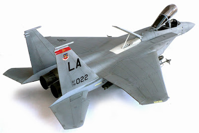
McDonnell Douglas F - 15 C Eagle

Here are some more images of Revell's 1/32 scale McDonnell Douglas F - 15 C Eagle.
From Wikipedia"
The McDonnell Douglas (now Boeing) F-15 Eagle is a twin-engine, all-weather tactical fighter designed to gain and maintain air superiority in aerial combat. It is considered among the most successful modern fighters with over 100 aerial combat victories with no losses in dogfights. Following reviews of proposals, the United States Air Force selected McDonnell Douglas' design in 1967 to meet the service's need for a dedicated air superiority fighter. The Eagle first flew in July 1972, and entered service in 1976. The F-15 is expected to be in service with the U.S. Air Force until 2025.
Since the 1970s, the Eagle has also been exported to Israel, Japan, and Saudi Arabia. Despite originally being envisioned as a pure air superiority aircraft, the design proved flexible enough that an all-weather strike derivative, the F-15E Strike Eagle, was later developed, and entered service in 1989.
F-15C
Improved single-seat all-weather air-superiority fighter version, 483 built 1979-85. The last 43 F-15Cs are being upgraded with AN/APG-70 radar.

Saturday, November 23, 2013

DeHavilland Mosquito Mk IV Bomber

Here are some images of Revell's 1/32 scale DeHavilland Mosquito Mk IV Bomber.

From Wikipedia"
The de Havilland DH.98 Mosquito was a British multi-role combat aircraft with a two-man crew that served during the Second World War and the postwar era. The Mosquito was one of the few operational front-line aircraft of the World War II era to be constructed almost entirely of wood and, as such, was nicknamed "The Wooden Wonder". The Mosquito was also known affectionately as the "Mossie" to its crews. Originally conceived as an unarmed fast bomber, the Mosquito was adapted to many other roles during the air war, including low- to medium-altitude daytime tactical bomber, high-altitude night bomber, pathfinder, day or night fighter, fighter-bomber, intruder, maritime strike aircraft, and fast photo-reconnaissance aircraft. It was also used by the British Overseas Airways Corporation (BOAC) as a transport.
When the Mosquito entered production in 1941, it was one of the fastest operational aircraft in the world. Entering widespread service in 1942, the Mosquito first operated as a high-speed, high-altitude photo-reconnaissance aircraft, and continued to operate in this role throughout the war. From mid-1942 to mid-1943 Mosquito bombers were used in high-speed, medium- or low-altitude missions, attacking factories, railways and other pinpoint targets within Germany and German-occupied Europe. From late 1943, Mosquito bomber units were formed into the Light Night Strike Force and used as pathfinders for RAF Bomber Command's heavy-bomber raids. They were also used as "nuisance" bombers, often dropping 4,000 lb (1,812 kg) "cookies", in high-altitude, high-speed raids that German night fighters were almost powerless to intercept.
As a night fighter, from mid-1942, the Mosquito was used to intercept Luftwaffe raids on the United Kingdom, most notably defeating the German aerial offensive, Operation Steinbock, in 1944. Offensively, starting in July 1942, some Mosquito night-fighter units conducted intruder raids over Luftwaffe airfields and, as part of 100 Group, the Mosquito was used as a night fighter and intruder in support of RAF Bomber Command's heavy bombers, and played an important role in reducing bomber losses during 1944 and 1945. As a fighter-bomber in the Second Tactical Air Force, the Mosquito took part in "special raids", such as the attack on Amiens Prison in early 1944, and in other precision attacks against Gestapo or German intelligence and security forces. Second Tactical Air Force Mosquitos also played an important role operating in tactical support of the British Army during the 1944 Normandy Campaign. From 1943 Mosquitos were used by RAF Coastal Command strike squadrons, attacking Kriegsmarine U-boats (particularly in the 1943 Bay of Biscay offensive, where significant numbers of U-boats were sunk or damaged) and intercepting transport ship concentrations.
The Mosquito saw service with the Royal Air Force (RAF) and many other air forces in the European theatre, and the Mediterranean and Italian theatres. The Mosquito was also used by the RAF in the South East Asian theatre, and by the Royal Australian Air Force (RAAF) based in the Halmaheras and Borneo during the Pacific War.

Mosquito B Mk IV Series 2, DK338, built in September 1942 and delivered to 105 Squadron, becoming GB-O.IWM Collection.
On 21 June 1941 the Air Ministry ordered that the last 10 Mosquitoes, ordered as photo-reconnaissance aircraft, should be converted to bombers. These 10 aircraft were part of the original 1 March 1940 production order and became the B Mk IV Series 1. W4052 was to be the prototype and flew for the first time on 8 September 1941.
The bomber prototype led to the B Mk IV, of which 273 were built: apart from the 10 Series 1s, all of the rest were built as Series 2s with extended nacelles, revised exhaust manifolds, with integrated flame dampers, and larger tailplanes. Series 2 bombers also differed from the Series 1 in having a larger bomb bay to increase the payload to four 500 lb (230 kg) bombs, instead of the four 250 pounds (110 kg) bombs of Series 1. This was made possible by shortening the tail of the 500 pounds (230 kg) bomb so that these four larger weapons could be carried (or a 2,000 lb (920;kg) total load). The B Mk IV entered service in May 1942 with 105 Squadron.
B Mk IV (modified) of No. 692 Squadron, showing bulged bomb bay doors to accommodate the 4,000lb "Cookie".
In April 1943 it was decided to convert a B Mk IV to carry a 4,000 lb (1,812 kg), thin-cased high explosive bomb (nicknamed "Cookie"). The conversion, including modified bomb bay suspension arrangements, bulged bomb bay doors and fairings, was relatively straightforward, and 54 B.IVs were subsequently modified and distributed to squadrons of RAF Bomber Command's Light Night Striking Force. 27 B Mk IVs were later converted for special operations with the Highball anti-shipping weapon, and were used by 618 Squadron, formed in April 1943 specifically to use this weapon. A B Mk IV, DK290 was initially used as a trials aircraft for the bomb, followed by DZ471,530 and 533. The B Mk IV had a maximum speed of 380 mph (610 km/h), a cruising speed of 265 mph (426 km/h), ceiling of 34,000 ft (10,000 m), a range of 2,040 nmi (3,780 km), and a climb rate of 2,500 ft per minute (762 m).
Other bomber variants of the Mosquito included the Merlin 21 powered B Mk V high-altitude version. Trials with this configuration were made with W4057 which had the wings strengthened and an addition of two fuel tanks, or alternatively two 500 pounds (230 kg) bombs. This design was not produced in Britain, but formed the basic design of the Canadian-built B.VII. Only W4057 was built in prototype form. The Merlin 31 powered B Mk VII was built by de Havilland Canada. It was based on the B.V. and first flown on 24 September 1942. It only saw service in Canada and only 25 were built. Six were handed over to the United States Army Air Forces.
B Mk IX (54 built) was powered by the Merlin 72,73, 76 or 77. The two-stage Merlin variant was based on the PR.IX. The prototype DK 324 was converted from a PR.VIII and first flew on 24 March 1943. In October 1943 it was decided that all B Mk IVs and all B Mk IXs then in service would be converted to carry the 4,000 pounds (1,800 kg) "Cookie", and all B Mk IXs built after that date were designed to allow them to be converted to carry the weapon. The B Mk IX had a maximum speed of 408 mph (657 km/h), an economical cruise speed of 295 mph (475 km/h) at 20,000 ft, and 350 mph (560 km/h) at 30,000 ft, ceiling of 36,000 ft (11,000 m), a range of 2,450 nmi (4,540 km), and a climb rate of 2,850 feet per minute (869 m). The IX could carry a maximum load of 2,000–4,000 lb (910–1,800 kg) of bombs. A Mosquito B Mk IX holds the record for the most combat operations flown by an Allied bomber in the Second World War. LR503, known as "F for Freddie" (from its squadron code letters, GB*F), first served with No. 109 and subsequently, No. 105 RAF squadrons. It flew 213 sorties during the war, only to crash at Calgary airport during the Eighth Victory Loan Bond Drive on 10 May 1945, two days after Victory in Europe Day, killing both the pilot, Flt. Lt. Maurice Briggs, DSO, DFC, DFM and navigator Fl. Off. John Baker, DFC and Bar.
The B Mk XVI was powered by the same variations as the B.IX. All B Mk XVIs were capable of being converted to carry the 4,000 pounds (1,800 kg) "Cookie". The two-stage powerplants were added along with a pressurised cabin. DZ540 first flew on 1 January 1944. The prototype was converted from a IV (402 built). The next variant, the B Mk XX, was powered by Packard Merlins 31 and 33s. It was the Canadian version of the IV. Altogether, 245 were built. The B Mk XVI had a maximum speed of 408 mph (657 km/h), an economical cruise speed of 295 mph (475 km/h) at 20,000 ft, and 350 mph (560 km/h) at 30,000 ft, ceiling of 37,000 ft (11,000 m), a range of 1,485 nmi (2,750 km), and a climb rate of 2,800 ft per minute (853 m). The type could carry 4,000 pounds (1,800 kg) of bombs.
The B.35 was powered by Merlin 113 and 114As. Some were converted to TT.35s (Target Tugs) and others were used as PR.35s (photo-reconnaissance). The B.35 had a maximum speed of 422 mph (679 km/h), a cruising speed of 276 mph (444 km/h), ceiling of 42,000 ft (13,000 m), a range of 1,750 nmi (3,240 km), and a climb rate of 2,700 ft per minute (823 m). A total of 174 B.35s were delivered up to the end of 1945. A further 100 were delivered from 1946 for a grand total of 274, 65 of which were built by Airspeed Ltd.