Translate

Tuesday, June 28, 2016

Curtiss F9C Sparrowhawk

Here are some images of Williams Bros 1/32 scale Curtiss F9C Sparrowhawk.
A lot of scraping scratching and filling on this one.

From Wikipedia"
The Curtiss F9C Sparrowhawk was a light 1930s biplane fighter aircraft that was carried by the United States Navy airships USS Akron and Macon. It is an example of a parasite fighter, a small airplane designed to be deployed from a larger aircraft such as an airship or bomber.

On 20 August 1929, off the coast of New Jersey, a biplane hooked itself to the bottom of a dirigible and was carried along by the larger craft. This is the 2nd such incident. The “snapon, snapoff” experiment is accomplished by the Navy airship USS Los Angeles, under Lt. Com. Herbert Wiley, and a Navy biplane. The biplane, regulating its speed to that of the dirigible, flew close under the Los Angeles. A large hook had been attached to the middle of the top wing of the biplane, and from the bottom of the Los Angeles hung a U-shaped yoke. Maneuvering the ship under the dirigible, the plane pilot slipped the hook into the Los Angeles’ yoke and for 3 or 4 minutes the dirigible carried the biplane. The plane pilot, by a cord arrangement in his cabin, withdrew the hook from the yoke and flew clear of the dirigible.
An F9C-2 captures the trapeze aboard Macon in 1933
Although designed as a pursuit plane or fighter, the Sparrowhawk's primary duty in service was reconnaissance, enabling the airships it served to search a much wider area of ocean. The Sparrowhawk was primarily chosen for service aboard the large rigid-framed airships Akron and Macon because of its small size (20.2 ft (6.2 m) long and with only a 25.5 ft (7.8 m) wingspan), though its weight, handling and range characteristics, and also downward visibility from the cockpit, were not ideal for its reconnaissance role. The theoretical maximum capacity of the airships' hangar was five aircraft, one in each hangar bay and one stored on the trapeze but, in the Akron, two structural girders obstructed the after two hangar bays, limiting her to a maximum complement of three Sparrowhawks. A modification to remove this limitation was pending at the time of the airship's loss. Macon had no such limitation and she routinely carried four airplanes.
To achieve launching and recovery from the airship in flight, a 'skyhook' system was developed. The Sparrowhawk had a hook mounted above its top wing that attached to the cross-bar of a trapeze mounted on the carrier airship. For launching, the biplane's hook was engaged on the trapeze inside the airship's (internal) hangar, the trapeze was lowered clear of the hull into the (moving) airship's slipstream and, engine running, the Sparrowhawk would then disengage its hook and fall away from the airship. For recovery, the biplane would fly underneath its mother ship, until beneath the trapeze, climb up from below, and hook onto the cross-bar. The width of the trapeze cross-bar allowed a certain lateral lee-way in approach, the biplane's hook mounting had a guide rail to provide protection for the turning propeller (see photo), and engagement of the hook was automatic on positive contact between hook and trapeze. More than one attempt might have to be made before a successful engagement was achieved, for example in gusty conditions. Once the Sparrowhawk was securely caught, it could then be hoisted by the trapeze back within the airship's hull, the engine being cut as it passed the hangar door. Although seemingly a tricky maneuver, pilots soon learned the technique and it was described as being much easier than landing on a moving, pitching and rolling aircraft carrier. Almost inevitably, the pilots soon acquired the epithet "The men on the Flying Trapeze" and their aircraft were decorated with appropriate unit emblems.
Once the system was fully developed, in order to increase their scouting endurance while the airship was on over-water operations, the Sparrowhawks would have their landing gear removed and replaced by a fuel tank. When the airship was returning to base, the biplanes' landing gear would be replaced so that they could land independently again.
For much of their service with the airships, the Sparrowhawks' effectiveness was greatly hampered by their poor radio equipment, and they were effectively limited to remaining within sight of the airship. However, in 1934 new direction-finding sets and new voice radios were fitted which allowed operations beyond visual range, exploiting the extended range offered by the belly fuel tanks and allowing the more vulnerable mother ship to stay clear of trouble.
One interesting use of the Sparrowhawks was to act as 'flying ballast'. The airship could take off with additional ballast or fuel aboard instead of its airplanes. Once the airship was cruising, the aircraft would be flown aboard, the additional weight being supported by dynamic lift until the airship lightened.

Only one intact Sparrowhawk survives today. BuAer number 9056 was pending write-off at NAS Hampton Roads in 1939 when it was transferred to the Smithsonian Institution. In later years it had been rebuilt, using parts from the surviving F9C-2 (BuAer number 9057) and the XF9C-2 (9264). It was previously at the National Museum of Naval Aviation, at NAS Pensacola, and is currently displayed at the Steven F. Udvar-Hazy Center of the Smithsonian's National Air and Space Museum collection, wearing the markings of F9C-2 A9056 of USS Macon.
The cockpit of one of the Macon's Sparrowhawk's, photographed in 2006. The ribs of the upper wing. and the pilot's telescopic gunsight can be seen.
The remains of a further four aircraft lie at the underwater wreck-site of the Macon; the aircraft were found in their hangar when the wreck was discovered and documented in 1990 and 1991. These are known to have been BuAer number 9058 - 9060.

Wednesday, June 8, 2016

Junkers Ju 87A (Stuka)

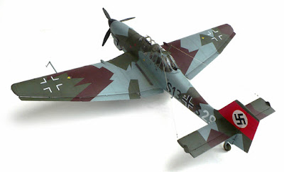
Here are some images of trumpeter's 1/32 scale Junkers Ju 87A (Stuka).

From Wikipedia"


Formation of Ju 87A dive-bombers, with the A's characteristic large wheel "trousers", each having one transverse bracing strut
The second prototype had a redesigned single vertical stabiliser and a 610 PS (449 kW or 602 hp) Junkers Jumo 210 A engine installed, and later the Jumo 210 Da. The first A series variant, the A-0, was of all-metal construction, with an enclosed cockpit under a "greenhouse" well-framed canopy; bearing twin radio masts on its aft sections, diagonally mounted to either side of the airframe's planform centreline and unique to the -A version. To ease the difficulty of mass production, the leading edge of the wing was straightened out and the ailerons' two aerofoil sections had smooth leading and trailing edges. The pilot could adjust the elevator and rudder trim tabs in flight, and the tail was connected to the landing flaps, which were positioned in two parts between the ailerons and fuselage. The A-0 also had a flatter engine cowling, which gave the pilot a much better field of vision. In order for the engine cowling to be flattened, the engine was set down nearly 0.25 m (9.8 in). The fuselage was also lowered along with the gunner's position, allowing the gunner a better field of fire.
The RLM ordered seven A-0s initially, but then increased the order to 11. Early in 1937, the A-0 was tested with varied bomb loads. The underpowered Jumo 210A, as pointed out by von Richthofen, was insufficient, and was quickly replaced with the Jumo 210D power plant.
The A-1 differed from the A-0 only slightly. As well as the installation of the Jumo 210D, the A-1 had two 220 L (60 US gal) fuel tanks built into the inner wing, but it was not armoured or protected. The A-1 was also intended to be fitted with a quartet of 7.92 mm (.312 in) MG 17 machine guns in its wings, but two of these - one per side - were omitted due to weight concerns; the pair that remained were fed a total of 500 rounds of ammunition, stored in the design's characteristic transverse strut-braced, large-planform undercarriage "trousers", not used on the Ju 87B versions and onward. The pilot relied on the Revi C 21C gun sight for the two MG 17s. The gunner had only a single 7.92 mm (.312 ) MG 15, with 14 drums of ammunition, each containing 75 rounds. This represented a 150-round increase in this area over the Ju 87 A-0. The A-1 was also fitted with a larger 3.3 m (11 ft) propeller.
The Ju 87 was capable of carrying a 500 kg (1,100 lb) bomb, but only if not carrying the rear gunner/radio operator as, even with the Jumo 210D power plant, the Ju 87 was still underpowered for operations with more than a 250 kg (550 lb) bomb load. All Ju 87 As were restricted to 250 kg (550 lb) weapons (although during the Spanish Civil War missions were conducted without the gunner).
The Ju 87 A-2 was retrofitted with the Jumo 210Da fitted with a two-stage supercharger. The only further significant difference between the A-1 and A-2 was the H-PA-III controllable-pitch propeller. By mid-1938, 262 Ju 87 As had been produced, 192 from the Junkers factory in Dessau, and a further 70 from Weser Flugzeugbau ("Weserflug" - WFG) in Lemwerder near Bremen. The new, more powerful, Ju 87B model started to replace the Ju 87A at this time.

Saturday, June 4, 2016

Supermarine Spitfire Mk. Vb/Trop

Here are some images of Trumpeter's 1/24 scale Supermarine Spitfire Mk. Vb/Trop.

From Wikipedia"
The VB became the main production version of the Mark Vs. Along with the new Merlin 45 series the B wing was fitted as standard. As production progressed changes were incorporated, some of which became standard on all later Spitfires. Production started with several Mk IBs which were converted to Mk VBs by Supermarine. Starting in early 1941 the round section exhaust stacks were changed to a "fishtail" type, marginally increasing exhaust thrust. Some late production VBs and VCs were fitted with six shorter exhaust stacks per side, similar to those of Spitfire IXs and Seafire IIIs; this was originally stipulated as applying specifically to VB(trop)s. After some initial problems with the original Mk I size oil coolers, a bigger oil cooler was fitted under the port wing; this could be recognised by a deeper housing with a circular entry. From mid-1941 alloy covered ailerons became a universal fitting.

Spitfire VC(trop), fitted with Vokes filters and "disc" wheels, of 417 Squadron RCAF in Tunisia in 1943.
A constant flow of modifications were made as production progressed. A "blown" cockpit hood, manufactured by Malcolm, was introduced in an effort to further increase the pilot's head-room and visibility. Many mid to late production VBs - and all VCs - used the modified, improved windscreen assembly with the integral bullet resistant centre panel and flat side screens introduced with the Mk III. Because the rear frame of this windscreen was taller than that of the earlier model the cockpit hoods were not interchangeable and could be distinguished by the wider rear framing on the hood used with the late-style windscreen.
Different propeller types were fitted, according to where the Spitfire V was built: Supermarine and Westland manufactured VBs and VCs used 10 ft 9 in (3.28 m) diameter, 3 bladed de Havilland constant speed units, with narrow metal blades, while Castle Bromwich manufactured VBs and VCs were fitted with a wide bladed Rotol constant speed propeller of either 10 ft 9 in (3.28 m) diameter, with metal blades, or (on late production Spitfires) 10 ft 3 in (3.12 m) diameter, with broader, "Jablo" (compressed wood) blades. The Rotol spinners were longer and more pointed than the de Havilland leading to a 3.5 in (8.9 cm) increase in overall length. The Rotol propellers allowed a modest speed increase over 20,000 ft (6,100 m) and an increase in the service ceiling. A large number of Spitfire VBs were fitted with "gun heater intensifier" systems on the exhaust stacks. These piped additional heated air into the gun bays. There was a short tubular intake on the front of the first stack and a narrow pipe led into the engine cowling from the rear exhaust.
The VB series were the first Spitfires able to carry a range of specially designed "slipper" drop tanks which were fitted underneath the wing centre-section. Small hooks were fitted, just forward of the inboard flaps: when the tank was released these hooks caught the trailing edge of the tank, swinging it clear of the fuselage.
With the advent of the superb Focke Wulf Fw 190 in August 1941 the Spitfire was for the first time truly outclassed, hastening the development of the "interim" Mk IX. In an effort to counter this threat, especially at lower altitudes, the VB was the first production version of the Spitfire to use "clipped" wingtips as an option, reducing the wingspan to 32 ft 2 in (9.8 m).The clipped wings increased the roll rate and airspeed at lower altitudes. Several different versions of the Merlin 45/50 family were used, including the Merlin 45M which had a smaller "cropped" supercharger impeller and boost increased to +18 lb. This engine produced 1,585 hp (1,182 kW) at 2,750 ft (838 m), increasing the L.F VB's maximum rate of climb to 4720 ft/min (21.6 m/s) at 2,000 ft (610 m).

VB Trop of 40 Squadron SAAF fitted with the "streamlined" version of the Aboukir filter, a broad-bladed, 10 ft 3 in (3.12 m) diameter Rotol propeller, and clipped wings.
The Mk VB(trop) (or type 352) could be identified by the large Vokes air filter fitted under the nose; the reduced speed of the air to the supercharger had a detrimental effect on the performance of the aircraft, reducing the top speed by 8 mph (13 km/h) and the climb rate by 600 ft/min (3.04 m/s), but the decreased performance was considered acceptable. This variant was also fitted with a larger oil tank and desert survival gear behind the pilot's seat. A new "desert" camouflage scheme was applied. Many VB(trop)s were modified by 103 MU (Maintenance Unit-RAF depots in which factory fresh aircraft were brought up to service standards before being delivered to squadrons) at Aboukir, Egypt by replacing the Vokes filter with locally manufactured "Aboukir" filters, which were lighter and more streamlined. Two designs of these filters can be identified in photos: one had a bulky, squared off filter housing while the other was more streamlined. These aircraft were usually fitted with the wide blade Rotol propeller and clipped wings.