Translate

Friday, January 11, 2013

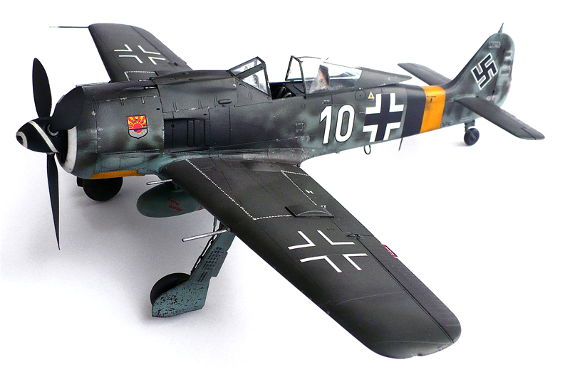
Focke Wulf FW 190 D-9

Here are some more images of Hasegawa's 1/32 scale Focke Wulf FW 190 D-9

From Wikipedia"
The Fw 190 D (nicknamed the Dora; or Long-Nose Dora, "Langnasen-Dora") was intended to improve on the high-altitude performance of the A-series enough to make it useful against the American heavy bombers of the era. In the event, the D series was rarely used against the heavy-bomber raids, as the circumstances of the war in late 1944 meant that fighter-versus-fighter combat and ground attack missions took priority. A total of 1,805 D-9s were produced. Production started in August 1944.
With the D version the power plant was changed from the radial engine of earlier models to an in-line 12-cylinder inverted-Vee liquid-cooled engine. The Jumo 213A generated 1,750 PS (1,726 hp, 1,287 kW), and could produce 2,100 PS (2,071 hp, 1,545 kW) of emergency power with MW 50 injection, improving performance to 426 mph (686 km/h) at 21,650 ft (6,600 m). In order to fit the new engine in the Fw 190 fuselage while maintaining proper balance, both the nose and the tail of the aircraft were lengthened, adding nearly 1.52 m (4.99 ft) to the fuselage, bringing the overall length to 10.192 m (33.438 ft) versus the 9.10 m (29.9 ft) of the late war A-9 series. The lengthened tail required a straight-sided bay, 30 cm (12 in) long, spliced in forward of the rear angled joint and tail assembly of the fuselage. To further aid balance, the pilot's oxygen bottles were moved aft and located in the new bay. This gave the rear fuselage a "stretched" appearance.
Furthermore, the move to a V12 engine from a radial engine required more components to be factored into the design, most significantly the need for coolant radiators (radial engines are air-cooled). To keep the design as simple and as aerodynamic as possible, Tank used an annular radiator (the AJA 180 L) installed at the front of the engine, similar to the configuration used in the Jumo powered versions of the Junkers Ju 88. The annular radiator with its adjustable cooling gills resembled a radial engine installation, although the row of six short exhausts stacks on either side of the elongated engine cowling showed that Jumo 213 was an inverted vee-12 engine. While the first few Doras were fitted with the flat-top canopy, these were later replaced with the newer rounded top "blown" canopy first used on the A-8 model. With the canopy changes, the shoulder and head armour plating design was also changed. Some late model Doras were also fitted with the Ta 152 vertical stabilizer and rudder, often called "Big Tails" by the Luftwaffe ground crews and pilots, as seen on W.Nr. 500647 Brown 4 from 7./JG 26 and W.Nr. 500645 Black 6 from JG 2. The centreline weapons rack was changed to an ETC 504 with a simplified and much smaller mounting and fairing.
Early D-9s reached service without the MW 50 installation, but in the meantime Junkers produced a kit to increase manifold pressure (Ladedrucksteigerungs-Rüstsatz) that increased engine output by 150 PS to 1,900 PS, and was effective up to 5,000 m (16,400 ft) altitude. It was fitted immediately to D-9s delivered to the units from September, or retrofitted in the field by TAM. By the end of December, all operational Doras, 183 in total, were converted. From November 1944, a simplified methanol water (MW 50) system (Oldenburg) was fitted, which boosted output to 2,100 PS. By the end of 1944, 60 were delivered with the simplified MW 50 system or were at the point of entering service. The 115 L tank of the Oldenburg system would hold the MW 50 booster liquid, which was single purpose, while later systems were to be dual purpose, holding either MW 50 or additional fuel.
The fighter lacked the high turn rate and higher rate of roll of its close coupled radial-engined predecessor. It was a bit faster, however, with a maximum speed of 680 km/h (422 mph) at 6,600 meters (21,650 ft). Its 2,240 horsepower with methanol-water injection (MW 50) gave it an excellent acceleration in combat situations. It also climbed and dived more rapidly than the Fw 190A, and so proved well suited to the dive-and-zoom ambush tactics favored by the Schlageter pilots. Many of the early models were not equipped with tanks for methanol, which was in very short supply in any event. At low altitude, the top speed and acceleration of these examples were inferior to those of Allied fighters. Hans Hartigs recalled that only one of the first batch of Dora 9s received by the First Gruppe had methanol water injection, and the rest had a top speed of only 590 km/h (360 mph).
Owing to the failure of multiple attempts to create an effective next-generation 190, as well as the comments of some Luftwaffe pilots, expectations of the Dora project were low. These impressions were not helped by the fact that Tank made it very clear that he intended the D-9 to be a stopgap until the Ta 152 arrived. These negative opinions existed for some time until positive pilot feedback began arriving at Focke-Wulf and the Luftwaffe command structure. Sporting good handling and performance characteristics, the D-9 made an effective medium altitude, high speed interceptor, although its performance still fell away at altitudes above about 20,000 ft (6,100 m). When flown by capable pilots, the Fw 190D proved the equal of Allied types.
As it was used in the anti-fighter role, armament in the "D" was generally lighter compared to that of the earlier aircraft—usually the outer wing cannon were dropped so that the armament consisted of two 13 mm (.51 in) MG 131, with 400 rounds per gun, and two 20 mm MG 151/20E cannon with 250 rounds per gun; all four weapons were synchronized to fire through the propeller arc. The wings of the D-9 still had the electrical circuits and attachment points for the underwing WGr 21 rocket propelled mortar, although none appeared to have used these operationally. While inferior to the A-series in roll rate, the "D" was superior in turn rate, climb, dive and horizontal speed. The Dora still featured the same wing as the A-8, however, and was capable of carrying outer wing cannon as well, as demonstrated by the D-11 variant, with a three-stage supercharger and four wing cannon (two MG 151s and two MK 108s). The first Fw 190 D-9s started entering service in September 1944, with III./JG 54. It was quickly followed by other units including I./JG 26 which flew its last operations on the A-8s on 19 November 1944.
Some Fw 190 Ds served as fighter cover for Me 262 airfields, as the jet fighters were very vulnerable on take-off and landing. These special units were known as Platzsicherungstaffel (airfield defence squadrons). One unit, known as the Würger-Staffel, was created in April 1945 by Leutnant Heinz Sachsenberg at the behest of Adolf Galland, and was part of JV 44. The role of the Staffel was to guard the airfield and JV 44's Messerschmitt Me 262s as they landed; as such the Fw 190s were supposed to take off before the jets and circle the airfield in pairs (a Rotte). However, to allow the 262s a clear run back to the airfield the 190s had to land before the jets, negating their protection. To help anti-aircraft artillery protecting the airfields to quickly identify friendly aircraft, the under-surfaces of the Würger-Staffel 190s were painted red with narrow white stripes. leading to the alternative nickname of Papageien Staffel (parrot squadron) from the bright red color.

Thursday, January 10, 2013

Mikoyan Gurevich MiG 3

Here are some more images of Trumpeter models 1/32  scale Mikoyan Gurevich MiG 3.
This aircraft flew with the 12 guards IAP  Air Defense of Moscow.

From Wikipedia"
The MiG-3's top speed of 640 km/h (398 mph) at 7,200 metres (23,622 ft) was faster than the 615 km/h (382 mph) of the German Messerschmitt Bf 109F-2 in service at the beginning of 1941 and the British Supermarine Spitfire V's 603 km/h (375 mph). At lower altitudes the MiG's speed advantage disappeared as its maximum speed at sea level was only 505 km/h (314 mph) while the Bf 109F-2 could do 515 km/h (320 mph). Unfortunately for the MiG-3 and its pilots, aerial combat over the Eastern Front generally took place at low and medium altitudes where it had no speed advantage.
The MiG's loaded weight of 3,350 kg (7,385 lb) was greater than the Bf 109F-2's 2,728 kg (6,014 lb) and it was less maneuverable in the horizontal plane than the Bf 109 due to its higher wing loading. This lack of maneuverability was exacerbated by the MiG-3's poor climb performance, its instability at high speeds (which can contribute to shell trajectory inaccuracy during a pursuit) and its weak armament.
The MiG-3's standard armament was one 12.7 mm (0.50 in) UBS machine gun and two 7.62 mm (0.30 in) ShKAS machine guns. This was a rather light armament by international standards, for example most versions of the German Messerschmitt Bf 109 that it encountered were equipped with one 20 mm (0.79 in) autocannon and two 7.92 mm (0.31 in) machine guns. To remedy this problem, 821 aircraft were built with one 12.7 mm UBK machine gun in a pod under each wing in mid-1941. This lowered its speed by about 20 km/h (12 mph) at all altitudes, which was unpopular with the pilots, some of whom removed the pods. One hundred aircraft were equipped with a pair of UBS machine guns in lieu of the ShKAS weapons. Another 215 aircraft also had just the UBS machine guns but were fitted to carry six RS-82 rockets. A total of 72 aircraft mounted a pair of 20 mm ShVAK cannon. A wide variety of armaments were experimented with by various units at the requests of their pilots or to make up shortages.

Wednesday, January 9, 2013

Fairey Swordfish Mk 1

Here are some images of Trumpeter Models 1/32 scale Fairey Swordfish Mk 1.

From Wikipedia"
The Fairey Swordfish was a torpedo bomber built by the Fairey Aviation Company and used by the Fleet Air Arm of the Royal Navy during the Second World War. Affectionately known as the "Stringbag" by its crews, it was outdated by 1939, but achieved some spectacular successes during the war, notably the sinking of one and damaging two battleships of the Regia Marina (the Italian Navy) in the Battle of Taranto and the famous crippling of the Bismarck. It was operated primarily as a fleet attack aircraft; however, during its later years, it was also used as an anti-submarine and training craft. Designed in the 1930s, the Swordfish outlived several types intended to replace it, and remained in front line service until VE Day.
The Swordfish was based on a Fairey design for the Greek Naval Air Service, who asked for a replacement of their Fairey IIIF Mk.IIIB's, and on Specifications M.1/30 and S.9/30, issued by Air Ministry, the work having been initiated as a Private Venture (PV). The company informed the Air Ministry of their work on the Greek order (that country's interest eventually waning) and proposed its solution to the requirements for a spotter-reconnaissance plane, spotter referring to observing the fall of a warship's gunfire. A subsequent Air Ministry Specification S.15/33, added the torpedo bomber role. The "Torpedo-Spotter-Reconnaissance" prototype TSR II (the PV was the TSR I) first flew on 17 April 1934. It was a large biplane with a metal airframe covered in fabric, and utilized folding wings as a space-saving feature for aircraft carrier use. An order was placed in 1935 and the aircraft entered service in 1936 with the Fleet Air Arm (then part of the RAF), replacing the Seal in the torpedo bomber role.
By 1939, the Fleet Air Arm (now under Royal Navy control) had 13 squadrons equipped with the Swordfish Mark I. There were also three flights of Swordfish equipped with floats, for use off aircraft catapult-equipped warships. One - from HMS Warspite — spotted fall of shot (i.e., radioed gunnery corrections back to the ship) during the Second Battle of Narvik in 1940 and subsequently sank the U-boat U-64. The Swordfish pioneered the use of Air to Surface Vessel radar ( ASV ), by carrier borne aircraft to locate surface ship targets at night and/or through clouds.
Swordfish flew from merchant aircraft carriers ("MAC ships"), 20 civilian cargo or tanker ships modified to carry three or four aircraft each, on anti-submarine duties with convoys. Three of these ships were Dutch manned, flying Swordfish from 860 (Dutch) Naval Air Squadron. The rest were manned by pilots and aircrew from 836 Naval Air Squadron, at one time the largest squadron with 91 aircraft.
Almost 2,400 had been built, 692 by Fairey and 1,699 in Sherburn by the Blackburn Aircraft Company, which were sometimes dubbed the "Blackfish". The most numerous version was the Mark II, of which 1,080 were made.

The primary weapon was the aerial torpedo, but the low speed of the biplane and the need for a long straight approach made it difficult to deliver against well-defended targets. Swordfish torpedo doctrine called for an approach at 5,000 ft (1,500 m) followed by a dive to torpedo release altitude of 18 ft (5.5 m). Maximum range of the early Mark XII torpedo was 1,500 yd (1400 m) at 40 knots (74 km/h) and 3,500 yd (3200 m) at 27 knots (50 km/h). The torpedo travelled 200 yd (180 m) forward from release to water impact, and required another 300 yd (270 m) to stabilise at preset depth and arm itself. Ideal release distance was 1,000 yd (900 m) from target if the Swordfish survived to that distance. Swordfish — flying from the British aircraft carrier HMS Illustrious — made a very significant strike on 11 November 1940 against the Italian navy during the Battle of Taranto, Italy, sinking or disabling three Italian battleships and a cruiser lying at anchor. In the aftermath, Taranto was visited by the Japanese naval attache from Berlin, who later briefed the staff who planned the attack on Pearl Harbor. Swordfish also flew anti-shipping sorties from Malta.
In May 1941, a Swordfish strike from HMS Ark Royal was vital in damaging the German battleship Bismarck, preventing it from escaping to France. The low speed of the attacking aircraft may have acted in their favour, as the planes were too slow for the fire-control predictors of the German gunners, whose shells exploded so far in front of the aircraft that the threat of shrapnel damage was greatly diminished as did the fact that some at least of the Swordfish flew so low that most of the Bismarck's flak weapons were unable to depress enough to hit them. The Swordfish aircraft scored two hits, one which did little damage but the other jammed Bismarck's rudders with 15° port helm on. making the warship unmanueverable and sealing its fate. The Bismarck was destroyed less than 13 hours later.

Swordfish torpedo bombers on the after deck of HMS Victorious before the attack on the Bismarck.
The problems with the aircraft were starkly demonstrated in February 1942 when a strike on German battleships during the Channel Dash resulted in the loss of all attacking aircraft, partly because only ten of the promised eighty-four fighters turned up to escort the six Swordfish. With the development of new torpedo attack aircraft, the Swordfish was soon redeployed successfully in an anti-submarine role, armed with depth-charges or eight "60 lb" (27 kg) RP-3 rockets and flying from the smaller escort carriers or even Merchant Aircraft Carriers (MAC) when equipped for rocket-assisted takeoff (RATO). Its low stall speed and inherently tough design made it ideal for operation from the MAC carriers in the often severe mid Atlantic weather. Indeed, its takeoff and landing speeds were so low that it did not require the carrier to be steaming into the wind, unlike most carrier-based aircraft. On occasion, when the wind was right, Swordfish were flown from a carrier at anchor.
Swordfish-equipped units accounted for 14 U-boats destroyed. The Swordfish was meant to be replaced by the Albacore, also a biplane, but actually outlived its intended successor. It was, finally, however, succeeded by the Fairey Barracuda monoplane torpedo bomber.
The last of 2,392 Swordfish aircraft was delivered in August 1944 and operational sorties continued in to January 1945 with anti-shipping operations off Norway (FAA Squadrons 835 and 813), where the Swordfish's manouvreability was essential. The last operational squadron was disbanded on 21 May 1945, after the fall of Germany; and the last training squadron was disbanded in the summer of 1946.
The Swordfish received the Stringbag nickname not because of its construction, but because of the seemingly endless variety of stores and equipment that the aircraft was cleared to carry. Crews likened the aircraft to a housewife's string shopping bag which was common at the time and, which due to its having no fixed shape, could adjust to hold any shape of packages. Like the shopping bag, the crews felt that the Swordfish could carry anything.

Tuesday, January 8, 2013

Arado Ar 196A-3 Seaplane

Here are some more images of Revell's 1/32 scale Arado Ar 196A-3 Seaplane.
You may have noticed that over the past while I have been posting models that have been posted here before, only with the prettier (and more professional) white background.
Gone are the days of the speckled grey linoleum (often confused for carpet).
Anyway during times when I have no models to build (I have the 1/350 TOS Enterprise sitting here, but I'm waiting for the lighting pack) I will be reposting some of my models with the pretty white (and more professional) background.

From Wikipedia"
The plane was loved by its pilots, who found it handled well both in the air and on the water. With the loss of the German surface fleet the A-1s were added to coastal squadrons, and continued to fly reconnaissance missions and submarine hunts into late 1944. Two notable operations were the capture of HMS Seal, and the repeated interception of RAF Armstrong-Whitworth Whitley bombers. Although it was no match for a fighter, it was considerably better than its Allied counterparts, and generally considered the best of its class. Owing to its good handling on water, the Finnish Air Force utilized Ar 196 solely on transporting and supplying special forces patrols behind enemy lines, landing on small lakes in remote areas. Several fully equipped soldiers were carried in the fuselage.

Arado in Allied hands

The first Arado Ar 196 to fall into allied hands was an example belonging to the German cruiser Admiral Hipper captured in Lyngstad by a Norwegian Marinens Flyvebaatfabrikk M.F.11 seaplane of the Trøndelag naval district on 8 April 1940, at the dawn of the Norwegian Campaign. After being towed to Kristiansund by the torpedo boat HNoMS Sild, it was used against its former owners, flying with Norwegian markings. At 0330 on April 18, the Arado was evacuated to the UK by a Royal Norwegian Navy Air Service pilot. The plane was shortly thereafter crashed by a British pilot while on transit to the Helensburgh naval air base for testing. At the end of the war, at least another Arado Ar 196 was left at a Norwegian airfield and kept in use as a liaison aircraft by the Royal Norwegian Air Force for a year on the West coast.

Monday, January 7, 2013

Nakajima Ki-84 Hayate (Frank) Prototype


Here are some more images of Hasegawa's 1/32 scale Nakajima Ki-84 Hayate (Frank) Prototype.

From Wikipedia"
 The Nakajima Ki-84 "Hayate" (キ84 疾風?) was a single-seat fighter used by the Imperial Japanese Army Air Force in World War II. The Allied reporting name was "Frank"; the Japanese Army designation was Army Type 4 Fighter (四式戦闘機 yon-shiki-sentō-ki?). Featuring excellent performance and high maneuverability, the Ki-84 was considered to be the best Japanese fighter to see large scale operations during World War II. It was able to match any Allied fighter, and to intercept the high-flying B-29 Superfortresses. Its powerful armament (that could include two 30 mm and two 20 mm cannon) increased its lethality. Though hampered by poor production quality in later models, a high-maintenance engine, a landing gear prone to buckle,and lack of experienced pilots above all else, Hayates proved to be fearsome opponents; 3,514 aircraft were built.

Design of the Ki-84 commenced in early 1942 to meet an Imperial Japanese Army Air Service requirement for a replacement to Nakajima's Ki-43 fighter, just entering service. The specification recognized the need to combine the maneuverability of the Ki-43 with performance to match the best western fighters and heavy firepower. The Ki-84 first flew in March 1943 Although the design itself was solid, the shortage of fuel, construction materials, poor production quality, and lack of skilled pilots prevented the fighter from reaching its potential.
The Ki-84 addressed the most common complaints about the popular and highly maneuverable Ki-43: insufficient firepower, poor defensive armor, and lack of climbing power. The Ki-84 was a cantilever low-wing monoplane of all-metal construction, except for the fabric-covered control surfaces. It had retractable tailwheel landing gear. Armament comprised two fuselage-mounted, synchronized 12.7 mm (.50 in) machine guns and two wing-mounted 20 mm cannon, a considerable improvement over the two 12.7 mm (.50 in) machine guns used in the Hayabusa. Defensive armor offered Hayate pilots better protection than the unsealed wing tanks and light-alloy airframe of the Ki-43. In addition, the Ki-84 used a 65 mm (2.56 in) armor-glass canopy, 13 mm (.51 in) of head and back armor, and multiple bulkheads in the fuselage, which protected both the methanol-water tank (used to increase the effectiveness of the supercharger) and the centrally located fuel tank.
It was the Nakajima Ha-45 radial powerplant that gave the Hayate its high speed and prowess in combat. Derived from the Homare engine common to many Japanese aircraft, the Hayate used a direct-injection version of the engine, using water injection to aid the supercharger in giving the Ki-84 a rated 1,491 kW (2,000 hp) at takeoff. This combination—in theory, at least—gave it a climb rate and top speed roughly competitive with the top Allied fighters. Initial Hayate testing at Tachikawa in early summer 1943 saw test pilot Lieutenant Funabashi reach a maximum level airspeed of 624 km/h (387 mph) in the second prototype. After the war, a late-production, captured example was tested in the US with high octane fuel, and achieved a speed of 687 km/h (426 mph).
The complicated direct-injection engine required a great deal of care in construction and maintenance and, as the Allies advanced toward the Japanese homeland, it became increasingly difficult to support the type's designed performance. Compounding reliability problems were the Allied submarine blockade which prevented delivery of crucial components, such as the landing gear. Many further landing gear units were compromised by the poor-quality heat treatment of late-war Japanese steel. Many Hayates consequently suffered strut collapses on landing. Further damage was caused by inadequately trained late war pilots.

Focke Wulf FW 190 A-8

Here are some more images of Hasegawa's 1/32 scale Focke Wulf FW 190 A-8.

From Wikipedia"
The Focke-Wulf Fw 190 Würger (Shrike) was a German Second World War single-seat, single-engine fighter aircraft designed by Kurt Tank in the late 1930s. Powered by a radial engine, the 190 had ample power and was able to lift larger loads than its well-known counterpart, the Messerschmitt Bf 109. The 190 was used by the Luftwaffe in a wide variety of roles, including day fighter, fighter-bomber, ground-attack aircraft and, to a lesser degree, night fighter.
When the Fw 190 started flying operationally over France in August 1941, it quickly proved itself to be superior in all but turn radius to the Royal Air Force's main front-line fighter, the Spitfire Mk. V. The 190 wrested air superiority away from the RAF until the introduction of the vastly improved Spitfire Mk. IX in July 1942 restored qualitative parity. The Fw 190 made its air combat debut on the Eastern Front in November/December 1942; though Soviet pilots considered the Bf 109 the greater threat, the Fw 190 made a significant impact. The fighter and its pilots proved just as capable as the Bf 109 in aerial combat, and in the opinion of German pilots who flew both, provided increased firepower and manoeuvrability at low to medium altitude.
The Fw 190 became the backbone of the Jagdwaffe (Fighter Force), along with the Bf 109. On the Eastern Front, the Fw 190 was versatile enough to use in Schlachtgeschwader (Battle Wings or Strike Wings), specialised ground attack units which achieved much success against Soviet ground forces. As an interceptor, the Fw 190 underwent improvements to make it effective at high altitude, enabling it to maintain relative parity with its Allied opponents. The Fw 190A series' performance decreased at high altitudes (usually 6,000 m (20,000 ft) and above), which reduced its effectiveness as a high-altitude interceptor, but this problem was mostly rectified in later models, particularly in the Junkers Jumo 213 inline-engine Focke-Wulf Fw 190D series, which was introduced in September 1944. In spite of its successes, it never entirely replaced the Bf 109.
The Fw 190 was well liked by its pilots. Some of the Luftwaffe's most successful fighter aces claimed a great many of their kills while flying it, including Otto Kittel, Walter Nowotny and Erich Rudorffer.

In autumn 1937, the German Ministry of Aviation asked various designers for a new fighter to fight alongside the Messerschmitt Bf 109, Germany's front line fighter. Although the Bf 109 was an extremely competitive fighter, the Ministry of Aviation was worried that future foreign designs might outclass it, and wanted to have new aircraft under development to meet these possible challenges.
Kurt Tank responded with a number of designs, most incorporating liquid-cooled inline engines. However, it was not until a design was presented using the air-cooled, 14-cylinder BMW 139 radial engine that the Ministry of Aviation's interest was aroused. As this design used a radial engine, it would not compete with the inline-powered Bf 109 for engines, when there were already too few DB 601's to go around. This was not the case for competing advanced designs like the Heinkel He 100 or Focke-Wulf Fw 187, where production would compete with the 109 or Messerschmitt Bf 110 for engine supplies. After the war, Tank denied a rumour that he had to "fight a battle" with the Ministry to convince them of the radial engine's merits.

At the time, the use of radial engines in land-based fighters was relatively rare in Europe, as it was believed that their large frontal area would cause too much drag on something as small as a fighter. Tank was not convinced of this, having witnessed the successful use of radial engines by the US Navy, and felt a properly streamlined installation would eliminate this problem.
The hottest point on any air-cooled engine are the cylinder heads, located along the outside diameter of a radial engine. In order to provide sufficient air to cool the engine, the cowling needed to allow airflow at this outer edge, which generally resulted in the majority of the front face of the engine being left open to the air. During the late 1920s, NACA led development of a dramatic improvement by placing an airfoil-shaped ring around the outside of the cylinder heads. The shaping accelerated the air as it entered the front of the cowl, increasing the total airflow, and allowing the opening in front of the engine to be made smaller.
Tank introduced a further refinement to this basic concept. He suggested placing most of the airflow components on the propeller itself, in the form of a oversized propeller spinner whose outside diameter was the same as the engine itself. The cowl around the engine proper was greatly simplified, essentially a basic cylinder. Air entered through a small hole at the center of the propeller, and was directed through ductwork in the spinner so it was blowing rearward along the cylinder heads. To provide enough airflow, a cone was placed in the center of the hole, over the propeller hub, which was intended to compress the airflow and allow a smaller hole to be used. In theory, the tight-fitting cowling also provided some thrust due to the compression and heating of air as it flowed through the cowling.
As to the rest of the design philosophy, Tank wanted something more than an aircraft built only for speed. Tank outlined the reasoning:

The Messerschmitt 109 and the British Spitfire, the two fastest fighters in world at the time we began work on the Fw 190, could both be summed up as a very large engine on the front of the smallest possible airframe; in each case armament had been added almost as an afterthought. These designs, both of which admittedly proved successful, could be likened to racehorses: given the right amount of pampering and easy course, they could outrun anything. But the moment the going became tough they were liable to falter. During World War I, I served in the cavalry and in the infantry. I had seen the harsh conditions under which military equipment had to work in wartime. I felt sure that a quite different breed of fighter would also have a place in any future conflict: one that could operate from ill-prepared front-line airfields; one that could be flown and maintained by men who had received only short training; and one that could absorb a reasonable amount of battle damage and still get back. This was the background thinking behind the Focke-Wulf 190; it was not to be a racehorse but a Dienstpferd, a cavalry horse.
One of the main features of the Fw 190 was its wide-tracked, inwards-retracting landing gear. Tank appreciated that operating from primitive airfields in wartime would require a stable undercarriage — a lesson learned from witnessing the difficulty of moving machinery in the First World War. The wide-track landing gear spacing gave it better ground handling characteristics, and it suffered fewer ground accidents than the Bf 109 with its narrow-track landing gear. The undercarriage was designed to withstand a sink rate of 15 feet per second (4.5 meters per second, 900 feet per minute), double the strength factor usually required. Hydraulic wheel brakes were used.
Most aircraft of the era used cables and pulleys to operate their controls. The cables tended to stretch, resulting in the sensations of "give" and "play" that made the controls less crisp and responsive, and required constant maintenance to correct. For the new design, the team replaced the cables with rigid pushrods and bearings to eliminate this problem. Another innovation was making the controls as light as possible. The maximum resistance of the ailerons was limited to eight pounds, as the average man's wrist could not exert a greater force. The empennage (tail assembly) featured relatively small and well-balanced horizontal and vertical surfaces.
The design team also attempted to minimize changes in the aircraft's trim at varying speeds, thus reducing the pilot's workload. They were so successful in this regard that they found in-flight-adjustable aileron and rudder trim tabs were not necessary. Small, fixed tabs were fitted to control surfaces and adjusted for proper balance during initial test flights. Only the elevator trim needed to be adjusted in flight (a feature common to all aircraft). This was accomplished by tilting the entire horizontal tailplane by an electric motor, with an angle of incidence ranging from -3° to +5°.
Another aspect of the new design was the extensive use of electrically powered equipment instead of the hydraulic systems used by most aircraft manufacturers of the time. On the first two prototypes, the main landing gear was hydraulic. Starting with the third prototype, the undercarriage was operated by push buttons controlling electric motors in the wings, and was kept in position by electric up and down-locks. The armament was also loaded and fired electrically. Tank believed that service use would prove that electrically powered systems were more reliable and more rugged than hydraulics, electric lines being much less prone to damage from enemy fire.
As was the case for the 109, the 190 featured a fairly small wing planform with relatively high wing loading. This presents a trade-off in performance; an aircraft with a smaller wing suffers less drag in most flight and therefore flies faster and may have better range. However, it also means the wing cannot generate extra lift as easily, which is needed for maneuvering or flight at high altitudes.The wings spanned 9.5 m (31 ft 2 in) and had an area of 15 m² (161 ft²). The wing was designed using the NACA 23015.3 airfoil at the root and the NACA 23009 airfoil at the tip.

Sunday, January 6, 2013

Messerschmitt BF 109 K-4

Here are some more images of Revell's (Hasegawa molds) 1/32 scale Messerschmitt BF 109 K-4.

From Wikipedia"
The Bf 109K was the last of the series to see operational duty and the last in the Bf 109 evolutionary line. The K series was a response to the bewildering array of series, models, modification kits and factory conversions for the Bf 109, which made production and maintenance complicated and costly – something Germany could ill-afford late in the war. The RLM ordered Messerschmitt to rationalise production of the Bf 109, consolidating parts, types, and so on, to produce a uniform, standard model with better interchangeability of parts and equipment. At the same time, the existing flaws of the design were to be remedied. Work on the new version began in the spring of 1943, and the prototype was ready by the autumn of that year. Series production started in August 1944 with the K-4 model, due to changes in the design and delays with the new DB 605D powerplant. The K-4 was the only version to be mass produced.
Externally the K series could be identified by changes in the locations of the radio equipment hatch, which was moved forward and to a higher position between frames four and five, and the filler point for the fuselage fuel tank, which was moved forward to a location between frames two and three. In addition, the D/F loop was moved aft to sit between frames three and four on the top fuselage spine and a small circular plate above the footstep on the port side of the fuselage was deleted. The rudder was fitted as standard with a Flettner tab and two fixed tabs although some rare examples were not fitted with the fixed tabs. All K-4s were to be fitted with a long retractable tailwheel (350 × 135 mm/14 × 5 in) with two small clamshell doors covering the recess when the tail-wheel was retracted.
The wings featured the large rectangular fairings for the large 660 × 190 mm (26 × 7 in) main wheels. Small wheel well doors, originally planned for the G series, were fitted to the outer ends of the wheel bays, covering the outer wheels when retracted. These doors were often removed by front-line units. The ailerons were fitted with small, adjustable trim tabs. The radio equipment was the FuG 16ZY with an antenna mast fitted under the port outer wing and FuG 25a IFF as well as the FuG 125 Hermine D/F equipment. Internally, the oxygen bottles were relocated from the rear fuselage to the right wing. Flettner tabs for the ailerons were also to be fitted to serial production aircraft to reduce control forces, but are only seen on photos of later production aircraft.
Armament of the K-4 consisted of a 30 mm (1.18 in) MK 108 engine-mounted cannon (Motorkanone) with 65 rounds, and two 13 mm (.51 in) MG 131s in the nose with 300 rpg although some K-4s were fitted with the MG 151/20 as the Motorkanone. Additional Rüstsätze, or equipment kits, such as a 300 L (80 US gal) drop tank (R III), bombs up to the size of 500 kg/1,100 lb (R I), underwing 20 mm Mauser MG 151/20 cannon gondola pods (R IV) or 21 cm (8 in) Wfr.Gr. 21 rockets (as on the Gustav models) could be carried after minimal preparations; the latter two however were rarely used by Bf 109 units at this stage of the war, but there is evidence that III./JG 26 were almost completely equipped with K-4s which were fitted with R IV. In addition there were problems with the 30 mm (1.18 in) MK 108 Motorkanone:
The 30mm cannon were extremely potent weapons, but they had a tendency to jam, and apparently all of the K-4s supplied to III./JG 26 were also equipped with 20 mm-guns in the hated underwing tubs. Uffz. Georg Genth's regular aircraft was a G-10, but on occasion he flew a K-4. He preferred the G-10 as a dogfighter, as the K-4's bulky armament sharply reduced its manouevrability.
Power was provided by a Daimler-Benz DB 605DM (early models - engine produced in limited numbers) and the DB 605DB/DC engine (production variants of the DM) with an emergency power rating of 1,600/1,800 PS at 6,000 m (1,160 PS maximum continual at 6,600 m), and take-off power of 1,800/2,0000 PS at 0 m. The DB and DM used MW50 methanol-water when running on B4 fuel, while the DC required C3 fuel with MW50 usage. A wide-chord, three bladed VDM 9-12159 propeller of 3 m diameter was used, as on the G-6/AS, G-14/AS and G-10.
Deliveries began in mid-October 1944. 534 examples had been delivered by the Messerschmitt A.G., Regensburg by the end of November 1944, and 856 by the end of the year. Regensburg delivered a total of 1593 by the end of March 1945, after which production figures are missing. With such a high rate of production, despite continuous heavy fighting, by the end of January 1945 314 K-4s – about every fourth 109 – were listed on hand with the 1st line Luftwaffe units. Ultimately it was intended to equip all Bf 109 units with the 109K, which marked the final stage of 109 development before the jet age.
The Bf 109 K-4 was the fastest 109 of World War II, reaching 710 km/h (440 mph) at 7,500 m (24,610 ft) altitude; improved propellers were being developed when the war ended which would have boosted the speed to 727 km/h (452 mph), and 741 km/h (459 mph) was expected with an experimental swept-back propeller design. The Rate of climb was 2,775 ft (850 m)/min.[101] The standard Revi 16C reflector sight was fitted, which was slated to be replaced later by the EZ 42 Gyro gunsight, although this never happened. The Bf 109 remained comparable to opposing fighters until the end of the war. However, the deteriorating ability of the thousands of novice Luftwaffe pilots by this stage of the war meant the 109's strengths were of little value against the numerous and well-trained Allied fighter pilots.
Several other versions were projected based on the 109K airframe – K-6, K-8, K-10 and K-14. In the proposed K-6 the armament would have been two 13 mm (.51 in) MG 131 above the engine, along with a 30 mm (1.18 in) MK 108 Motorkanone and an internally mounted MK 108 in each wing, with 45 rpg. Alternatively, the wing MK 108s could be substituted by 20 mm MG 151/20s, with 100 rpg. Armour weight was increased to 200 lb (91 kg). Takeoff weight was 7,986 lb (3,622 kg). Some K-6 prototypes were built and tested at the Erprobungstelle Tarnewitz weapons-testing centre on the Baltic coast.
Project drawings of the K-8 show an K-series airframe powered by the two-stage DB 605L high altitude engine, a high-velocity 30 mm (1.18 in) MK 103mot Motorkanone, and two 30 mm (1.18 in) MK 108 cannons in the wings; the cowl 13 mm (.51 in) MG 131s were dispensed with.
Some sources point to limited use of the K-14, intended as high-altitude heavy fighter. Two airframes are listed as delivered to II./JG52 under Major Wilhelm Batz in late spring of 1945, these being armed with only one 30 mm (1.18 in) cannon, but the type's existence cannot be positively confirmed. The K-14 was to be powered by the two-stage supercharged DB 605L engine, the use of a four-bladed propeller 460 mph (740 km/h), and an operational altitude of 38,000 ft (12,000 m) was projected. Armour and armament were otherwise similar to the K-6.

Tuesday, January 1, 2013

38 cm SK C/34 Naval Guns With Turret

Here are some images of Trumpeter Models 1/200 scale 38 cm SK C/34 Naval Guns with Turret.
This is the bonus kit that comes with the Bismarck kit.

From Wikipedia"
The 38 cm S.K. C/34 Naval gun was developed by Germany mid to late 1930s. It armed the Bismarck-class battleships and was planned as the armament of the O class battlecruisers and the re-armed Scharnhorst-class battleships. Six twin-gun mountings were also sold to the Soviet Union and it was planned to use them on the Kronshtadt-class battlecruisers, however they were never delivered. Spare guns were used as coastal artillery in Denmark, Norway and France. One gun is currently on display at Møvig Fortress outside Kristiansand.
 The data given is according Krupp datasheet 38 cm S.K.C/34 e WA52-453(e). This gun was mounted in pairs in the Drh.L. C/34e turret which allowed elevation from -5° 30' to +30°. Each gun had an individual cradle, spaced 3.5 metres (11 ft) apart, but they were normally coupled together. In general the turret was hydraulically-powered, but the training gear, auxiliary elevation, auxiliary hoists and some loading gear was electrically powered. The turrets weighed 1,048 tonnes (1,031 long tons; 1,155 short tons) to 1,056 tonnes (1,039 long tons; 1,164 short tons), rested on ball bearings on a 8.75 metres (28.7 ft) diameter track, could elevate 6° per second and traverse 5.4° per second. The guns were loaded at +2.5° and used a telescoping chain-operated rammer. According to German manuals the required permanent capacity for the loading equipment for ammunition was 2.5 shells per minute. During testing period at the Baltic Sea the AVKS Report states an output of the ammunition delivery system up to 3.125 shells per minute. Under battle conditions Bismarck averaged roughly one round per minute in her battle with HMS Hood and Prince of Wales.
 Sixteen guns were used for the Bismarck and Tirpitz and six were ordered for the Gneisenau when it was to be re-armed in 1942. Six were intended for each of the O class battlecruisers, but it is uncertain how many of these last were actually delivered. Six mountings with twelve guns were sold to the Soviet Union who planned to use them on two Kronshtadt-class battlecruisers, but these were never delivered. Surplus guns were used as coast defense guns.