Translate

Saturday, January 6, 2018

Sopwith Triplane

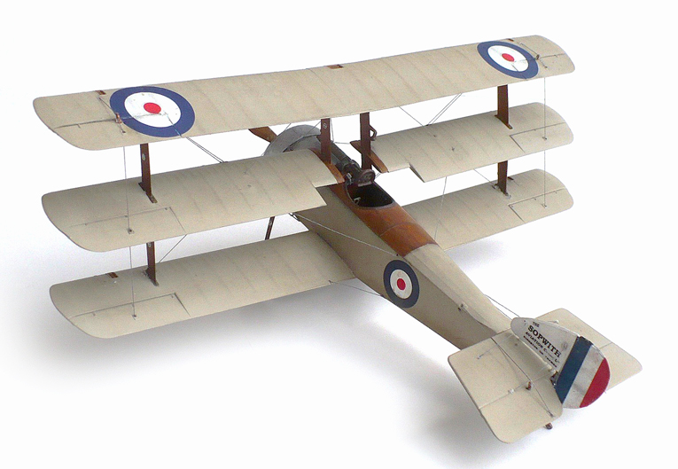
Here are some images of Roden's 1/32 scale Sopwith Triplane.
The plane represented here is the N500 prototype.

From Wikipedia"

 The Sopwith Triplane was a British single seat fighter aircraft designed and manufactured by the Sopwith Aviation Company during the First World War. It was the first military triplane to see operational service. The Triplane joined Royal Naval Air Service squadrons in early 1917 and was immediately successful. It was nevertheless built in comparatively small numbers and was withdrawn from active service as Sopwith Camels arrived in the latter half of 1917. Surviving Triplanes continued to serve as operational trainers until the end of the war.

The Triplane began as a private venture by the Sopwith Aviation Company. The fuselage and empennage closely mirrored those of the earlier Pup, but chief engineer Herbert Smith gave the new aircraft three narrow-chord wings to provide the pilot with an improved field of view. Ailerons were fitted to all three wings. By using the variable incidence tailplane, the aircraft could be trimmed to fly hands-off. The introduction of a smaller 8 ft span tailplane in February 1917 improved elevator response.
The Triplane was initially powered by the 110 hp Clerget 9Z nine-cylinder rotary engine, but most production examples were fitted with the 130 hp Clerget 9B rotary. At least one Triplane was tested with a 110 hp Le Rhône rotary engine, but this did not provide a significant improvement in performance.
The initial "prototype of what was to be referred to simply as the Triplane" first flew on 28 May 1916, with Sopwith test pilot Harry Hawker at the controls. Within three minutes of takeoff, Hawker startled onlookers by looping the aircraft, serial N500, three times in succession. The Triplane was very agile, with effective, well-harmonised controls. When maneuvering, however, the Triplane presented an unusual appearance. One observer noted that the aircraft looked like "a drunken flight of steps" when rolling.
In July 1916, N500 was sent to Dunkirk for evaluation with "A" Naval Squadron, 1 Naval Wing. It proved highly successful. The second prototype, serial N504, was fitted with a 130 hp Clerget 9B. N504 first flew in August 1916 and was eventually sent to France in December. This aircraft served as a conversion trainer for several squadrons.


Between July 1916 and January 1917, the Admiralty issued two contracts to Sopwith for a total of 95 Triplanes, two contracts to Clayton & Shuttleworth Ltd. for a total of 46 aircraft, and one contract to Oakley & Co. Ltd. for 25 aircraft. Seeking modern aircraft for the Royal Flying Corps, the War Office also issued a contract to Clayton & Shuttleworth for 106 Triplanes. In February 1917, the War Office agreed to exchange its Triplane orders for the Admiralty's SPAD S.VII contracts.
Production commenced in late 1916. Sopwith and Clayton & Shuttleworth completed their RNAS production orders, but Oakley, which had no prior experience building aircraft, delivered only three Triplanes before its contract was cancelled in October 1917. For unknown reasons, the RFC Triplane contract issued to Clayton & Shuttleworth was simply cancelled rather than being transferred to the RNAS. Total production amounted to 147 aircraft.

No. 1 Naval Squadron became fully operational with the Triplane by December 1916, but the squadron did not see any significant action until February 1917, when it relocated from Furnes to Chipilly.[14] No. 8 Naval Squadron received its Triplanes in February 1917. Nos. 9 and 10 Naval Squadrons equipped with the type between April and May 1917. The only other major operator of the Triplane was a French naval squadron based at Dunkirk, which received 17 aircraft.
The Triplane's combat debut was highly successful. The new fighter's exceptional rate of climb and high service ceiling gave it a marked advantage over the Albatros D.III, though the Triplane was slower in a dive. The Germans were so impressed by the performance of the Triplane that it spawned a brief triplane craze among German aircraft manufacturers. Their efforts resulted in no fewer than 34 different prototypes, including the Fokker V.4, prototype of the successful Fokker Dr.I.
Pilots nicknamed the aircraft the Tripehound or simply the Tripe. The Triplane was famously flown by "B" Flight 10 Naval Squadron, better known as "Black Flight". This all-Canadian flight was commanded by the ace Raymond Collishaw. Their aircraft, named Black Maria, Black Prince, Black George, Black Death and Black Sheep, were distinguishable by their black-painted fins and cowlings. Black Flight claimed 87 German aircraft in three months while equipped with the Triplane. Collishaw scored 34 of his eventual 60 victories in the aircraft, making him the top Triplane ace.
The Triplane's combat career was comparatively brief, in part because the Triplane proved difficult to repair. The fuel and oil tanks were inaccessible without dismantling the wings and fuselage. Even relatively minor repairs had to be made at rear echelon repair depots. Spare parts became difficult to obtain during the summer of 1917, resulting in the reduction of No. 1 Naval Squadron's complement from 18 to 15 aircraft.
The Triplane also gained a reputation for structural weakness because the wings of some aircraft collapsed in steep dives. This defect was attributed to the use of light gauge bracing wires in the 46 aircraft built by subcontractor Clayton & Shuttleworth. Several pilots of No. 10 Naval Squadron used cables or additional wires to strengthen their Triplanes. In 1918, the RAF issued a technical order for the installation of a spanwise compression strut between the inboard cabane struts of surviving Triplanes. One aircraft, serial N5912, was fitted with additional mid-bay flying wires on the upper wing while used as a trainer.
Another drawback of the Triplane was its light armament. Contemporary Albatros fighters were armed with two guns but most Triplanes carried one synchronised Vickers machine gun. Efforts to fit twin guns to the Triplane met with mixed results. Clayton & Shuttleworth built six experimental Triplanes with twin guns. Some of these aircraft saw combat service with Nos. 1 and 10 Naval Squadrons in July 1917 but performance was reduced and the single gun remained standard. Triplanes built by Oakley would have featured twin guns, an engineering change which severely delayed production.
In June 1917, No. 4 Naval Squadron received the first Sopwith Camels and the advantages of the sturdier, better-armed fighter quickly became evident. Nos. 8 and 9 Naval Squadrons re-equipped with Camels between early July and early August 1917. No. 10 Naval Squadron converted in late August, turning over its remaining Triplanes to No. 1 Naval Squadron. No. 1 operated Triplanes until December, suffering heavy casualties as a consequence. By the end of 1917, surviving Triplanes were used as advanced trainers with No. 12 Naval Squadron.

Survivors and modern reproductions

Canada
  • Reproduction – Reserve Hanger, Canada Aviation and Space Museum in Ottawa, Ontario. This Triplane is a reproduction of N5492 RNAS "Black Maria" (Raymond Collishaw) built by American amateur airplane-maker Carl R. Swanson between 1963 and 1966. The Museum purchased it in 1966, and provided and installed its Clerget 9B rotary engine. Wing Commander Paul A. Hartman piloted the aircraft during its first flight, on May 5, 1967 at Rockcliffe airport. It remained airworthy and flew on special occasions until 1971.
Russia
  • N5486 – On static display at the Central Air Force Museum in Monino, Moscow. It was supplied to the Russian Government for evaluation in May 1917. In Russia, the aircraft was fitted with skis and used operationally until captured by the Bolshevists. The aircraft then served in the Red Air Force, probably as a trainer, and was rebuilt many times.
United Kingdom

Friday, January 5, 2018

Fokker D. VI

Here are some images of Roden's 1/32 scale Fokker D. VI.

From Wikipedia"

The Fokker D.VI was a German fighter aircraft built in limited numbers at the end of World War I. The D.VI served in the German and Austro-Hungarian air services.


In late 1917, Fokker-Flugzeugwerke built two small biplane prototypes designated V.13. These aircraft combined a set of scaled-down D.VII wings with a fuselage and empennage closely mirroring those of the earlier Dr.I. The first prototype utilized an 82 kW (110 hp) Oberursel Ur.II rotary engine, while the second featured a 119 kW (160 hp) Siemens-Halske Sh.III bi-rotary engine.
Fokker submitted both prototypes at the Adlershof fighter trials in late January 1918. At that time, Fokker reengined the first prototype with the 108 kW (145 hp) Oberursel Ur.III. Pilots found the V.13s to be maneuverable and easy to fly. Idflieg issued a production contract after the V.13s were ultimately judged to be the best rotary powered entries of the competition.


The new aircraft, designated D.VI, passed its Typenprüfung (official type test) on 15 March 1918. The production aircraft utilized the Oberursel Ur.II, which was the only readily available German rotary engine. Idflieg authorized low level production pending availability of the more powerful Goebel Goe.III. Deliveries commenced in April and ceased in August, after only 59 aircraft had been completed. Seven aircraft were delivered to the Austro-Hungarian Air Service (Luftfahrtruppen).
In service, the D.VI was hampered by the low power of the Oberursel Ur.II. Moreover, the lack of castor oil and the poor quality of "Voltol," an ersatz lubricant, severely reduced engine life and reliability. The D.VI remained in frontline service until September 1918, and continued to serve in training and home defense units until the Armistice.

Wednesday, January 3, 2018

Supermarine Spitfire Mk XIV C

Here are some images of Revell/AA Productions 1/32 scale Supermarine Spitfire Mk XIV C in India markings.

From Wikipedia"
The first Griffon-powered Spitfires suffered from poor high altitude performance due to having only a single stage supercharged engine. By 1943, Rolls-Royce engineers had developed a new Griffon engine, the 61 series, with a two-stage supercharger. In the end it was a slightly modified engine, the 65 series, which was used in the Mk XIV. The resulting aircraft provided a substantial performance increase over the Mk IX. Although initially based on the Mk VIII airframe, common improvements made in aircraft produced later included the cut-back fuselage and tear-drop canopies, and the E-Type wing with improved armament.
The Mk XIV differed from the Mk XII in that the longer, two-stage supercharged Griffon 65, producing 2,050 hp (1,528 kW), was mounted 10 inches (25.4 cm) further forward. The top section of the engine bulkhead was angled forward, creating a distinctive change of angle to the upper cowling's rear edge. A new five bladed Rotol propeller of 10 ft 5 in (3.18 m) in diameter was used, although one prototype JF321 was fitted with a six bladed contra rotating unit. The "fishtail" design of ejector exhaust stub gave way to ones of circular section. The increased cooling requirements of the Griffon engine meant that all radiators were much bigger and the underwing housings were deeper than previous versions.
The cowling fasteners were new, flush fitting "Amal" type and there were more of them. The oil tank (which had been moved from the lower cowling location of the Merlin engine variants to forward of the fuselage fuel tanks) was increased in capacity from 6 to 10 gal.
To help balance the new engine, the radio equipment was moved further back in the rear fuselage and the access hatch was moved from the left fuselage side to the right. Better VHF radio equipment allowed for the aerial mast to be removed and replaced by a "whip" aerial further aft on the fuselage spine. Because the longer nose and the increased slipstream of the big five-bladed propeller a new tail unit with a taller, broader fin and a rudder of increased area was adopted.
The first batch of aircraft to fly with the Griffon 60 series engines were six converted Mk VIIIs JF316 to JF321 which were called Mk VIIIG. The first one of these was flown by Jeffrey Quill on 20 January 1943,
Changes to the aircraft were restricted to those essential to enable it to accept the new engine ... I found that it had a spectacular performance doing 445 mph at 25,000 ft, with a sea-level rate of climb of over 5,000 ft per minute. I remember being greatly delighted with it; it seemed to me that from this relatively simple conversion, carried out with a minimum of fuss and bother, had come up with something quite outstanding ... The MK VIIIG, with virtually the same tail surfaces both vertical and horizontal as the Merlin MK VIII, was very much over-powered and the handling in the air was unacceptable for an operational type ... I soon realised that a new throttle box would be needed giving a much greater angular travel for the hand lever ... The next essential ... was an improvement in the directional stability and control and a new fin was drawn out with a substantial increase in area (7.42 sq. ft) and a much larger rudder and fitted to the second aircraft JF317. This, though not ideal, produced a very marked improvement in directional characteristics and we were able to introduce minor changes thereafter and by various degrees of trimmer tab and balance tab to reach an acceptable degree of directional stability and control. The enlarged fin of JF317 had a straight leading edge but for production a more elegant curved line was introduced.
— Quill
One prototype, JF321, was fitted and tested with a Rotol six-bladed contra-rotating propeller unit; although this promised to eliminate the characteristic swing on take-off (caused by the propeller slipstream) the propeller unit was prone to failure. The pitch control mechanism controlled the pitch on the front propeller,
... and this was transmitted to the rear propeller (which was rotating in the opposite direction) through the transitional bearing mechanism. If this failed the pitch of the rear propeller was no longer under control and might do anything which was potentially dangerous.
— Quill
A similar contra-rotating propeller unit was later used on production Seafire 46 and 47s.
When the new fighter entered service with 610 Squadron in December 1943 it was a leap forward in the evolution of the Spitfire. Jeffrey Quill flew the first production aircraft, RB140 in October 1943:
So the Mk XIV was in business, and a very fine fighter it was. It fully justified the faith of those who, from the early days in 1939, had been convinced that the Griffon engine would eventually see the Spitfire into a new lease of life ... It was a splendid aeroplane in every respect. We still had some work to do to improve its longitudinal and directional characteristics, but it was powerful and performed magnificently. The only respect in which the XIV fell short was in its range.
— Quill
The Mk XIV could climb to 20,000 ft (6,100 m) in just over five minutes and its top speed, which was achieved at 25,400 ft (7,700 m), was 446 mph (718 km/h).
In operational service many pilots initially found that the new fighter could be difficult to handle, particularly if they were used to earlier Spitfire marks. Don Healy of 17 Squadron, based at Madura recalled that the Mk XIV was;
...a hairy beast to fly and took some getting used to. I personally preferred the old Mk Vs from a flying standpoint ... Even with full aileron, elevator and rudder, this brute of a fighter took off slightly sideways.
In spite of the difficulties pilots appreciated the performance increases. Wing Commander Peter Brothers, O/C Culmhead Wing in 1944–1945 and a Battle of Britain veteran;
It was truly an impressive machine, being able to climb almost vertically – it gave many Luftwaffe pilots the shock of their lives when, having thought they had bounced you from a superior height, they were astonished to find the Mk XIV climbing up to tackle them head-on, throttle wide open!
F Mk XIVs had a total of 109.5 gal of fuel consisting of 84 gal in two main tanks and a 12.5 imp gal fuel tank in each leading edge wing tank; other 30, 45, 50 or 90 gal drop tanks could be carried. The fighter's maximum range was just a little over 460 miles (740 km) on internal fuel, since the new Griffon engine consumed much more fuel per hour than the original Merlin engine of earlier variants. By late 1944, Spitfire XIVs were fitted with an extra 33 gal in a rear fuselage fuel tank, extending the fighter's range to about 850 miles (1,370 km) on internal fuel and a 90 gal drop tank. Mk XIVs with "tear-drop" canopies had 64 gal. As a result, F and FR Mk XIVEs had a range that was increased to over 610 miles (980 km), or 960 miles (1,540 km) with a 90 gal drop tank.
The first test of the aircraft was in intercepting V1 flying bombs and the Mk XIV was the most successful of all Spitfire marks in this role. When 150 octane fuel was introduced in mid-1944 the "boost" of the Griffon engine was able to be increased to +25 lbs (80.7"), allowing the top speed to be increased by about 30 mph (26 kn; 48 km/h) to 400 mph (350 kn; 640 km/h) at 2,000 ft (610 m).
The Mk XIV was used by the 2nd Tactical Air Force as their main high-altitude air superiority fighter in northern Europe with six squadrons operational by December 1944.
One problem which did arise in service was localised skin wrinkling on the wings and fuselage at load attachment points; although Supermarine advised that the Mk XIVs had not been seriously weakened, nor were they on the point of failure, the RAF issued instructions in early 1945 that all F and FR Mk XIVs were to be refitted with clipped wings.
Spitfire XIVs began to arrive in the South-East Asian Theatre in June 1945, too late to operate against the Japanese. It was this type which was rumoured to have been buried at an airfield in Burma after the war.


Monday, January 1, 2018

Supermarine Seafire Mk XV

Here are some images of Revell/AA Productions Supermarine Seafire Mk XV (early).
This aircraft served in No. 883 squadron RCN Dartmouth, Nova Scotia, Canada 1947.

From Wikipedia"
The Supermarine Seafire was a naval version of the Supermarine Spitfire adapted for operation from aircraft carriers. In concept, it is relatively comparable to the Hawker Sea Hurricane, a navalised version of the Spitfire's stablemate, the Hawker Hurricane. The name Seafire had been derived from the abbreviation of the longer name Sea Spitfire.
The idea of adopting a navalised carrier-capable version of the Supermarine Spitfire had been mooted by the Admiralty as early as May 1938. Despite a pressing need to replace various types of obsolete aircraft that were still in operation with the Fleet Air Arm (FAA), some opposed the notion, such as Winston Churchill, although these disputes were often a result of an overriding priority being placed on maximising production of land-based Spitfires instead. During 1941 and early 1942, the concept was again pushed for by the Admiralty, cumulating in an initial batch of Seafire Mk Ib fighters being provided in late 1941, which were mainly used for pilots to gain experience operating the type at sea. While there were concerns over the low strength of its undercarriage, which had not been strengthened like many naval aircraft would have been, its performance was found to be acceptable.
From 1942 onwards, further Seafire models were quickly ordered, including the first operationally-viable Seafire F Mk III variant. This led to the type rapidly spreading throughout the FAA. In November 1942, the first combat use of the Seafire occurred during in Operation Torch, the Allied landings in North Africa. In July 1943, the Seafire was used to provide air cover for the Allied invasion of Sicily; and reprised this role in September 1943 during the subsequent Allied invasion of Italy. During 1944, the type was again used in quantity to provide aerial support to Allied ground forces during the Normandy landings and Operation Dragoon in Southern France. During the latter half of 1944, the Seafire became a part of the aerial component of the British Pacific Fleet, where it quickly proved to be a capable interceptor against the feared kamikaze attacks by Japanese pilots which had become increasingly common during the final years of the Pacific War.
The Seafire continued to be used for some time after the end of the war. The FAA opted to promptly withdraw all of its Merlin-powered Seafires and replace them with Griffon-powered counterparts. The type saw further active combat use during the Korean War, in which FAA Seafires performed hundreds of missions in the ground attack and combat air patrol roles against North Korean forces during 1950. The Seafire was withdrawn from service during the 1950s. In FAA service, the type had been replaced by the newer Hawker Sea Fury, the last piston engine fighter to be used by the service, along with the first generation of jet-propelled naval fighters, such as the de Havilland Vampire, Supermarine Attacker, and Hawker Sea Hawk.
 After the Mk III series, the next Seafire variant to appear was the Seafire F Mk XV, which was powered by a Griffon VI – single-stage supercharger, rated at 1,850 hp (1,379 kW) at 2,000 ft (610 m) driving a 10 ft 5 in Rotol propeller. Designed in response to Specification N.4/43 this appeared to be a naval Spitfire F Mk XII; in reality the Mk XV was an amalgamation of a strengthened Seafire III airframe and wings with the wing fuel tanks, retractable tailwheel, larger elevators and broad-chord "pointed" rudder of the Spitfire VIII. The engine cowling was different to that of the Spitfire XII series, being secured with a larger number of fasteners and lacking the acorn shaped blister behind the spinner. The final 30 Mk XVs were built with the blown "teardrop" cockpit canopy and cut down rear fuselage introduced on the Spitfire Mk XVI. On the first 50 aircraft manufactured by Cunliffe-Owen a heavier, strengthened A-frame arrestor hook was fitted to cope with the greater weight. On subsequent Mk XVs a new form of "sting" type arrestor hook was used; this version was attached to the reinforced rudder post at the rear of the fuselage and was housed in a fairing below the base of the shortened rudder. A vee-shaped guard forward of the tailwheel prevented arrestor wires getting tangled up with the tailwheel. 390 Seafire XVs were built by Cunliffe-Owen and Westland from late 1944. Six prototypes had been built by Supermarine.

Wednesday, December 20, 2017

Thursday, December 14, 2017

!3th Century Medieval Wheel Clock

Here are some images of Lindberg Models 1/1 scale 13th Century Medieval Wheel Clock. Or was that 15th Century? I guess it would depend on what release you buy.
Now if I can only get the darn thing to work.

From Wikipedia"
The verge (or crown wheel) escapement is the earliest known type of mechanical escapement, the mechanism in a mechanical clock that controls its rate by allowing the gear train to advance at regular intervals or 'ticks'. Its origin is unknown. Verge escapements were used from the 14th century until the mid 19th century in clocks and pocketwatches. The name verge comes from the Latin virga, meaning stick or rod.
Its invention is important in the history of technology, because it made possible the development of all-mechanical clocks. This caused a shift from measuring time by continuous processes, such as the flow of liquid in water clocks, to repetitive, oscillatory processes, such as the swing of pendulums, which had the potential to be more accurate. Oscillating timekeepers are used in all modern timepieces.

The verge escapement dates from 13th-century Europe, where its invention led to the development of the first all-mechanical clocks. Starting in the 13th century, large tower clocks were built in European town squares, cathedrals, and monasteries. They kept time by using the verge escapement to drive the foliot, a primitive type of balance wheel, causing it to oscillate back and forth. The foliot was a horizontal bar with weights on the ends, and the rate of the clock could be adjusted by sliding the weights in or out on the bar.
The verge probably evolved from the alarum, which used the same mechanism to ring a bell and had appeared centuries earlier. There has been speculation that Villard de Honnecourt invented the verge escapement in 1237 with an illustration of a strange mechanism to turn an angel statue to follow the sun with its finger, but the consensus is that this was not an escapement.
It is believed that sometime in the late 13th century the verge escapement mechanism was applied to tower clocks, creating the first mechanical clock. In spite of the fact that these clocks were celebrated objects of civic pride which were written about at the time, it may never be known when the new escapement was first used. This is because it has proven difficult to distinguish from the meager written documentation which of these early tower clocks were mechanical, and which were water clocks; the same Latin word, horologe, was used for both. None of the original mechanisms have survived unaltered. Sources differ on which was the first clock 'known' to be mechanical, depending on which manuscript evidence they regard as conclusive. One candidate is the Dunstable Priory clock in Bedfordshire, England built in 1283, because accounts say it was installed above the rood screen, where it would be difficult to replenish the water needed for a water clock. Another is the clock built at the Palace of the Visconti, Milan, Italy, in 1335. However, there is agreement that mechanical clocks existed by the late 13th century.
The earliest description of an escapement, in Richard of Wallingford's 1327 manuscript Tractatus Horologii Astronomici on the clock he built at the Abbey of St. Albans, was not a verge, but a variation called a 'strob' escapement. It consisted of a pair of escape wheels on the same axle, with alternating radial teeth. The verge rod was suspended between them, with a short crosspiece that rotated first in one direction and then the other as the staggered teeth pushed past. Although no other example is known, it is possible that this design preceded the verge in clocks.
For the first two hundred years or so of the clock's existence, the verge was the only escapement used in mechanical clocks. In the sixteenth century alternative escapements started to appear, but the verge remained the most used escapement for 350 years until mid-17th century advances in mechanics, which also resulted in the invention of the pendulum.  Since clocks were valuable, after the invention of the pendulum many verge clocks were rebuilt to use this more accurate timekeeping technology, so very few of the early verge and foliot clocks have survived unaltered to the present day.
How accurate the first verge and foliot clocks were is debatable, with estimates of one to two hours error per day being mentioned, although modern experiments with clocks of this construction show accuracies of minutes per day were achievable. Early verge clocks were probably no more accurate than the previous water clocks, but they did not freeze in winter and were a more promising technology for innovation. By the mid-17th century, when the pendulum replaced the foliot, the best verge and foliot clocks had achieved an accuracy of 15 minutes per day.
 Most of the gross inaccuracy of the early verge and foliot clocks was not due to the escapement itself, but to the foliot oscillator. The first use of pendulums in clocks around 1656 suddenly increased the accuracy of the verge clock from hours a day to minutes a day. Most clocks were rebuilt with their foliots replaced by pendulums, to the extent that it is difficult to find original verge and foliot clocks intact today. A similar increase in accuracy in verge watches followed the introduction of the balance spring in 1658.

The verge escapement consists of a wheel shaped like a crown, with sawtooth-shaped teeth protruding axially toward the front, and with its axis oriented horizontally. In front of it is a vertical rod, the verge, with two metal plates, the pallets, that engage the teeth at opposite sides of the crown wheel. The pallets are not parallel, but are oriented with an angle in between them so only one catches the teeth at a time. The balance wheel (or the pendulum) is mounted at the end of the verge rod. As the clock's gears turn the crown wheel, one of its teeth pushes on a pallet, rotating the verge in one direction, and rotating the second pallet into the path of the teeth on the opposite side of the wheel, until the tooth pushes past the first pallet. Then a tooth on the wheel's opposite side contacts the second pallet, rotating the verge back the other direction, and the cycle repeats. The result is to change the rotary motion of the wheel to an oscillating motion of the verge. Each swing of the foliot or pendulum thus allows one tooth of the escape wheel to pass, advancing the wheel train of the clock by a fixed amount, moving the hands forward at a constant rate.
The crown wheel must have an odd number of teeth for the escapement to function. With an even number, two opposing teeth will contact the pallets at the same time, jamming the escapement. The usual angle between the pallets was 90° to 105°, resulting in a foliot or pendulum swing of around 80° to 100°. In order to reduce the pendulum's swing to make it more isochronous, the French used larger pallet angles, upwards of 115°. This reduced the pendulum swing to around 50° and reduced recoil (below), but required the verge to be located so near the crown wheel that the teeth fell on the pallets very near the axis, reducing initial leverage and increasing friction, thus requiring lighter pendulums.
As might be expected from its early invention, the verge is the most inaccurate of the widely used escapements. It suffers from these problems:
  • Verge watches and clocks are sensitive to changes in the drive force; they slow down as the mainspring unwinds. This is called lack of isochronism. It was much worse in verge and foliot clocks due to the lack of a balance spring, but is a problem in all verge movements. In fact, the standard method of adjusting the rate of early verge watches was to alter the force of the mainspring. The cause of this problem is that the crown wheel teeth are always pushing on the pallets, driving the pendulum (or balance wheel) throughout its cycle; it is never allowed to swing freely. All verge watches and spring driven clocks required fusees to equalize the force of the mainspring to achieve even minimal accuracy.
  • The escapement has "recoil", meaning that the momentum of the foliot or pendulum pushes the crown wheel backward momentarily, causing the clock's wheel train to move backward, during part of its cycle. This increases friction and wear, resulting in inaccuracy. One way to tell whether an antique watch has a verge escapement is to observe the second hand closely; if it moves backward a little during each cycle, the watch is a verge. This is not necessarily the case in clocks, as there are some other pendulum escapements which exhibit recoil.
  • In pendulum clocks, the wide pendulum swing angles of 80°-100° required by the verge cause an additional lack of isochronism due to circular error.
  • The wide pendulum swings also cause a lot of air friction, reducing the accuracy of the pendulum, and requiring a lot of power to keep it going, increasing wear. So verge pendulum clocks had lighter bobs, which reduced accuracy.
  • Verge timepieces tend to accelerate as the crown wheel and the pallets wear down. This is particularly evident in verge watches from the mid-18th century onwards. It is not in the least unusual for these watches, when run today, to gain many hours per day, or to simply spin as if there were no balance present. The reason for this is that as new escapements were invented, it became the fashion to have a thin watch. To achieve this in a verge watch requires the crown wheel to be made very small, magnifying the effects of wear.

Verge escapements were used in virtually all clocks and watches for 400 years. Then the increase in accuracy due to the introduction of the pendulum and balance spring in the mid 17th century focused attention on error caused by the escapement. By the 1820s, the verge was superseded by better escapements, though many examples of mid 19th century verge watches exist, as they were much cheaper by this time.
In pocketwatches, besides its inaccuracy, the vertical orientation of the crown wheel and the need for a bulky fusee made the verge movement unfashionably thick. French watchmakers adopted the thinner cylinder escapement, invented in 1695. In England, high end watches went to the duplex escapement, developed in 1782, but inexpensive verge fusee watches continued to be produced until the mid 19th century, when the lever escapement took over. These later verge watches were colloquially called 'turnips' because of their bulky build.
The verge was only used briefly in pendulum clocks before it was replaced by the anchor escapement, invented around 1660 and widely used beginning in 1680. The problem with the verge was that it required the pendulum to swing in a wide arc of 80° to 100°. Christiaan Huygens in 1674 showed that a pendulum swinging in a wide arc is an inaccurate timekeeper, because its period of swing is sensitive to small changes in the drive force provided by the clock mechanism.
Although the verge is not known for accuracy, it is capable of it. The first successful marine chronometers, H4 and H5, made by John Harrison in 1759 and 1770, used verge escapements with diamond pallets., In trials they were accurate to within a fifth of a second per day.
Today the verge is seen only in antique or antique-replica timepieces. Many original bracket clocks have their Victorian-era anchor escapement conversions undone and the original style of verge escapement restored. Clockmakers call this a verge reconversion.

Tuesday, December 12, 2017

The work of Gord Arnold

Gord Arnold built this Pershing diorama in 1/35 scale with resin figures.
Next we have Gord's Revell 1/25 scale 1970 Torino Cobra 429 Super Cobra Jet.
Next  here is Gord's Conversion using a Motor City Resin body over an AMT 1969 Cobra Fastback model kit. Very nice indeed. The paint is Metallic Indian Fire Red by Model Car World. It's a lacquer that is pre-mixed and ready for the air brush.

Friday, December 8, 2017

8 Years

8 years and counting since I started this blog and I have you to thank for its continuation. Here's to many more.

Thursday, December 7, 2017

Jeannin Stahltaube 1914

Here are some images of Wingnut Wings 1/32 scale Jeannin Stahltaube 1914.

From Wikipedia"
The Etrich Taube, also known by the names of the various later manufacturers who build versions of the type, such as the Rumpler Taube, was a pre-World War I monoplane aircraft. It was the first military aeroplane to be mass-produced in Germany.
The Taube was very popular prior to the First World War, and it was also used by the air forces of Italy and Austria-Hungary. Even the Royal Flying Corps operated at least one Taube in 1912. On November 1, 1911, Giulio Gavotti, an Italian aviator, dropped the world's first aerial bomb from his Taube monoplane over the Ain Zara oasis in Libya. Once the war began, it quickly proved inferior as a serious warplane and as a result was soon replaced by newer and more effective designs.

The Taube was designed in 1909 by Igo Etrich of Austria-Hungary, and first flew in 1910. It was licensed for serial production by Lohner-Werke in Austria and by Edmund Rumpler in Germany, now called the Etrich-Rumpler-Taube. Rumpler soon changed the name to Rumpler-Taube, and stopped paying royalties to Etrich, who subsequently abandoned his patent.
Despite its name, the Taube's unique wing form was not modeled after a dove, but was copied from the seeds of Alsomitra macrocarpa, which can fly long distances from their parent tree. Similar wing shapes were also used by Karl Jatho and Frederick Handley Page. Etrich had tried to build a flying wing aircraft based on the Zanonia wing shape, but the more conventional Taube type, with tail surfaces, was much more successful.
Etrich adopted the format of crosswind-capable main landing gear that Louis Blériot had used on his Blériot XI cross-channel monoplane for better ground handling. The wing has three spars and was braced by a cable-braced steel tube truss (called a "bridge", or Brücke in German) under each wing: at the outer end the uprights of this structure were lengthened to rise above the upper wing surfaces, to form kingposts to carry bracing and warping wires for the enlarged wingtips. A small landing wheel was sometimes mounted on the lower end of this kingpost, to protect it for landings and to help guard against ground loops.
Later Taube-type aircraft from other manufacturers would eventually replace the Blériot-style crosswind main gear with a simpler V-strut main gear format, and also omitted the underwing "bridge" structure for somewhat better aerodynamic efficiency.
Like many contemporary aircraft, especially monoplanes, the Taube used wing warping rather than ailerons for lateral (roll) control, and also warped the rear half of the stabilizer for use as an elevator control surface's function. Only the vertical, twinned triangular rudder surfaces were usually hinged.

The design provided for very stable flight, which made it extremely suitable for observation. In addition, the translucent wings made it difficult for ground observers to detect a Taube at an altitude above 400 meters. The first hostile engagement was by an Italian Taube in 1911 in Libya, its pilot using pistols and dropping 2 kg (4.4 lb) grenades. The Taube was also used for bombing in the Balkans in 1912–13, and in late 1914 when German 3 kg (6.6 lb) bomblets and propaganda leaflets were dropped over Paris. Taube spotter planes detected the advancing Imperial Russian Army in East Prussia during the World War I Battle of Tannenberg.
In civilian use, the Taube was used by pilots to win the Munich-Berlin Kathreiner prize. On 8 December 1911, Gino Linnekogel and Suvelick Johannisthal achieved a two-man endurance record for flying a Taube 4 hours and 35 minutes over Germany.
While initially there were two Taube aircraft assigned to Imperial German units stationed at Qingdao, China only one was available at the start of the war due to an accident. The Rumpler Taube piloted by Lieutenant Gunther Plüschow had to face the attacking Japanese, who had with them a total of eight aircraft. On October 2, 1914, Plüschow's Taube attacked the Japanese warshipswith two small bombs, but failed to score any hits. On November 7, 1914, shortly before the fall of Qingdao, Plüschow was ordered to fly top secret documents to Shanghai, but was forced to make an emergency landing at Lianyungang in Jiangsu, where he was interned by a local Chinese force. Plüschow was rescued by local Chinese civilians under the direction of an American missionary, and successfully reached his destination at Shanghai with his top secret documents, after giving the engine to one of the Chinese civilians who rescued him.
Poor rudder and lateral control made the Taube difficult and slow to turn. The aeroplane proved to be a very easy target for the faster and more mobile Allied fighters of World War I, and just six months into the war, the Taube had been removed from front line service to be used to train new pilots. Many future German aces would learn to fly in a Rumpler Taube.Due to the lack of license fees, no less than 14 companies built a large number of variations of the initial design, making it difficult for historians to determine the exact manufacturer based on historical photographs. 

The Technisches Museum Wien is thought to have the only known remaining Etrich-built example of the Taube in existence, an early enough example to have a four-cylinder engine powering it, and is potentially a twin to Gavotti's Taube aircraft from 1911, also said to have been powered with a four-cylinder inline engine. Other examples of original Taubes exist, such as one in Norway, which was the last original Taube to fly under its own power in 1922, over a Norwegian fjord.
The Owl's Head Transportation Museum in Owls Head, Maine USA, is so far the only known museum to attempt the construction of a flyable reproduction of the Etrich Taube in North America. Their example first flew in 1990, and it still flies today with the power of a 200 hp Ranger L-440 inline-6 "uprighted" air-cooled engine.

Tuesday, December 5, 2017

The Work Of Michael Evans

Here is a funny diorama by Regina modeler Mike Evans. It is called Zombie Apocalypse. He assembled some cattle stealing ufos, now available zombie figures, and some converted solders in 1/35 to make an exciting scene. One fact that I really like about Mr. Evan's work is that he is not afraid to be political.
Next  A couple of bums are standing next to an old wreck in 1/25 scale. I like the graffiti on the car.