Translate

Tuesday, June 28, 2016

Curtiss F9C Sparrowhawk

Here are some images of Williams Bros 1/32 scale Curtiss F9C Sparrowhawk.
A lot of scraping scratching and filling on this one.

From Wikipedia"
The Curtiss F9C Sparrowhawk was a light 1930s biplane fighter aircraft that was carried by the United States Navy airships USS Akron and Macon. It is an example of a parasite fighter, a small airplane designed to be deployed from a larger aircraft such as an airship or bomber.

On 20 August 1929, off the coast of New Jersey, a biplane hooked itself to the bottom of a dirigible and was carried along by the larger craft. This is the 2nd such incident. The “snapon, snapoff” experiment is accomplished by the Navy airship USS Los Angeles, under Lt. Com. Herbert Wiley, and a Navy biplane. The biplane, regulating its speed to that of the dirigible, flew close under the Los Angeles. A large hook had been attached to the middle of the top wing of the biplane, and from the bottom of the Los Angeles hung a U-shaped yoke. Maneuvering the ship under the dirigible, the plane pilot slipped the hook into the Los Angeles’ yoke and for 3 or 4 minutes the dirigible carried the biplane. The plane pilot, by a cord arrangement in his cabin, withdrew the hook from the yoke and flew clear of the dirigible.
An F9C-2 captures the trapeze aboard Macon in 1933
Although designed as a pursuit plane or fighter, the Sparrowhawk's primary duty in service was reconnaissance, enabling the airships it served to search a much wider area of ocean. The Sparrowhawk was primarily chosen for service aboard the large rigid-framed airships Akron and Macon because of its small size (20.2 ft (6.2 m) long and with only a 25.5 ft (7.8 m) wingspan), though its weight, handling and range characteristics, and also downward visibility from the cockpit, were not ideal for its reconnaissance role. The theoretical maximum capacity of the airships' hangar was five aircraft, one in each hangar bay and one stored on the trapeze but, in the Akron, two structural girders obstructed the after two hangar bays, limiting her to a maximum complement of three Sparrowhawks. A modification to remove this limitation was pending at the time of the airship's loss. Macon had no such limitation and she routinely carried four airplanes.
To achieve launching and recovery from the airship in flight, a 'skyhook' system was developed. The Sparrowhawk had a hook mounted above its top wing that attached to the cross-bar of a trapeze mounted on the carrier airship. For launching, the biplane's hook was engaged on the trapeze inside the airship's (internal) hangar, the trapeze was lowered clear of the hull into the (moving) airship's slipstream and, engine running, the Sparrowhawk would then disengage its hook and fall away from the airship. For recovery, the biplane would fly underneath its mother ship, until beneath the trapeze, climb up from below, and hook onto the cross-bar. The width of the trapeze cross-bar allowed a certain lateral lee-way in approach, the biplane's hook mounting had a guide rail to provide protection for the turning propeller (see photo), and engagement of the hook was automatic on positive contact between hook and trapeze. More than one attempt might have to be made before a successful engagement was achieved, for example in gusty conditions. Once the Sparrowhawk was securely caught, it could then be hoisted by the trapeze back within the airship's hull, the engine being cut as it passed the hangar door. Although seemingly a tricky maneuver, pilots soon learned the technique and it was described as being much easier than landing on a moving, pitching and rolling aircraft carrier. Almost inevitably, the pilots soon acquired the epithet "The men on the Flying Trapeze" and their aircraft were decorated with appropriate unit emblems.
Once the system was fully developed, in order to increase their scouting endurance while the airship was on over-water operations, the Sparrowhawks would have their landing gear removed and replaced by a fuel tank. When the airship was returning to base, the biplanes' landing gear would be replaced so that they could land independently again.
For much of their service with the airships, the Sparrowhawks' effectiveness was greatly hampered by their poor radio equipment, and they were effectively limited to remaining within sight of the airship. However, in 1934 new direction-finding sets and new voice radios were fitted which allowed operations beyond visual range, exploiting the extended range offered by the belly fuel tanks and allowing the more vulnerable mother ship to stay clear of trouble.
One interesting use of the Sparrowhawks was to act as 'flying ballast'. The airship could take off with additional ballast or fuel aboard instead of its airplanes. Once the airship was cruising, the aircraft would be flown aboard, the additional weight being supported by dynamic lift until the airship lightened.

Only one intact Sparrowhawk survives today. BuAer number 9056 was pending write-off at NAS Hampton Roads in 1939 when it was transferred to the Smithsonian Institution. In later years it had been rebuilt, using parts from the surviving F9C-2 (BuAer number 9057) and the XF9C-2 (9264). It was previously at the National Museum of Naval Aviation, at NAS Pensacola, and is currently displayed at the Steven F. Udvar-Hazy Center of the Smithsonian's National Air and Space Museum collection, wearing the markings of F9C-2 A9056 of USS Macon.
The cockpit of one of the Macon's Sparrowhawk's, photographed in 2006. The ribs of the upper wing. and the pilot's telescopic gunsight can be seen.
The remains of a further four aircraft lie at the underwater wreck-site of the Macon; the aircraft were found in their hangar when the wreck was discovered and documented in 1990 and 1991. These are known to have been BuAer number 9058 - 9060.

Wednesday, June 8, 2016

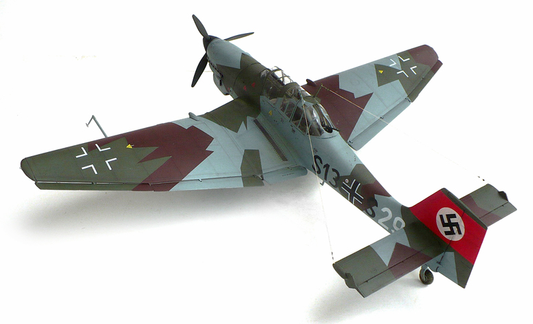
Junkers Ju 87A (Stuka)

Here are some images of trumpeter's 1/32 scale Junkers Ju 87A (Stuka).

From Wikipedia"


Formation of Ju 87A dive-bombers, with the A's characteristic large wheel "trousers", each having one transverse bracing strut
The second prototype had a redesigned single vertical stabiliser and a 610 PS (449 kW or 602 hp) Junkers Jumo 210 A engine installed, and later the Jumo 210 Da. The first A series variant, the A-0, was of all-metal construction, with an enclosed cockpit under a "greenhouse" well-framed canopy; bearing twin radio masts on its aft sections, diagonally mounted to either side of the airframe's planform centreline and unique to the -A version. To ease the difficulty of mass production, the leading edge of the wing was straightened out and the ailerons' two aerofoil sections had smooth leading and trailing edges. The pilot could adjust the elevator and rudder trim tabs in flight, and the tail was connected to the landing flaps, which were positioned in two parts between the ailerons and fuselage. The A-0 also had a flatter engine cowling, which gave the pilot a much better field of vision. In order for the engine cowling to be flattened, the engine was set down nearly 0.25 m (9.8 in). The fuselage was also lowered along with the gunner's position, allowing the gunner a better field of fire.
The RLM ordered seven A-0s initially, but then increased the order to 11. Early in 1937, the A-0 was tested with varied bomb loads. The underpowered Jumo 210A, as pointed out by von Richthofen, was insufficient, and was quickly replaced with the Jumo 210D power plant.
The A-1 differed from the A-0 only slightly. As well as the installation of the Jumo 210D, the A-1 had two 220 L (60 US gal) fuel tanks built into the inner wing, but it was not armoured or protected. The A-1 was also intended to be fitted with a quartet of 7.92 mm (.312 in) MG 17 machine guns in its wings, but two of these - one per side - were omitted due to weight concerns; the pair that remained were fed a total of 500 rounds of ammunition, stored in the design's characteristic transverse strut-braced, large-planform undercarriage "trousers", not used on the Ju 87B versions and onward. The pilot relied on the Revi C 21C gun sight for the two MG 17s. The gunner had only a single 7.92 mm (.312 ) MG 15, with 14 drums of ammunition, each containing 75 rounds. This represented a 150-round increase in this area over the Ju 87 A-0. The A-1 was also fitted with a larger 3.3 m (11 ft) propeller.
The Ju 87 was capable of carrying a 500 kg (1,100 lb) bomb, but only if not carrying the rear gunner/radio operator as, even with the Jumo 210D power plant, the Ju 87 was still underpowered for operations with more than a 250 kg (550 lb) bomb load. All Ju 87 As were restricted to 250 kg (550 lb) weapons (although during the Spanish Civil War missions were conducted without the gunner).
The Ju 87 A-2 was retrofitted with the Jumo 210Da fitted with a two-stage supercharger. The only further significant difference between the A-1 and A-2 was the H-PA-III controllable-pitch propeller. By mid-1938, 262 Ju 87 As had been produced, 192 from the Junkers factory in Dessau, and a further 70 from Weser Flugzeugbau ("Weserflug" - WFG) in Lemwerder near Bremen. The new, more powerful, Ju 87B model started to replace the Ju 87A at this time.

Saturday, June 4, 2016

Supermarine Spitfire Mk. Vb/Trop

Here are some images of Trumpeter's 1/24 scale Supermarine Spitfire Mk. Vb/Trop.

From Wikipedia"
The VB became the main production version of the Mark Vs. Along with the new Merlin 45 series the B wing was fitted as standard. As production progressed changes were incorporated, some of which became standard on all later Spitfires. Production started with several Mk IBs which were converted to Mk VBs by Supermarine. Starting in early 1941 the round section exhaust stacks were changed to a "fishtail" type, marginally increasing exhaust thrust. Some late production VBs and VCs were fitted with six shorter exhaust stacks per side, similar to those of Spitfire IXs and Seafire IIIs; this was originally stipulated as applying specifically to VB(trop)s. After some initial problems with the original Mk I size oil coolers, a bigger oil cooler was fitted under the port wing; this could be recognised by a deeper housing with a circular entry. From mid-1941 alloy covered ailerons became a universal fitting.

Spitfire VC(trop), fitted with Vokes filters and "disc" wheels, of 417 Squadron RCAF in Tunisia in 1943.
A constant flow of modifications were made as production progressed. A "blown" cockpit hood, manufactured by Malcolm, was introduced in an effort to further increase the pilot's head-room and visibility. Many mid to late production VBs - and all VCs - used the modified, improved windscreen assembly with the integral bullet resistant centre panel and flat side screens introduced with the Mk III. Because the rear frame of this windscreen was taller than that of the earlier model the cockpit hoods were not interchangeable and could be distinguished by the wider rear framing on the hood used with the late-style windscreen.
Different propeller types were fitted, according to where the Spitfire V was built: Supermarine and Westland manufactured VBs and VCs used 10 ft 9 in (3.28 m) diameter, 3 bladed de Havilland constant speed units, with narrow metal blades, while Castle Bromwich manufactured VBs and VCs were fitted with a wide bladed Rotol constant speed propeller of either 10 ft 9 in (3.28 m) diameter, with metal blades, or (on late production Spitfires) 10 ft 3 in (3.12 m) diameter, with broader, "Jablo" (compressed wood) blades. The Rotol spinners were longer and more pointed than the de Havilland leading to a 3.5 in (8.9 cm) increase in overall length. The Rotol propellers allowed a modest speed increase over 20,000 ft (6,100 m) and an increase in the service ceiling. A large number of Spitfire VBs were fitted with "gun heater intensifier" systems on the exhaust stacks. These piped additional heated air into the gun bays. There was a short tubular intake on the front of the first stack and a narrow pipe led into the engine cowling from the rear exhaust.
The VB series were the first Spitfires able to carry a range of specially designed "slipper" drop tanks which were fitted underneath the wing centre-section. Small hooks were fitted, just forward of the inboard flaps: when the tank was released these hooks caught the trailing edge of the tank, swinging it clear of the fuselage.
With the advent of the superb Focke Wulf Fw 190 in August 1941 the Spitfire was for the first time truly outclassed, hastening the development of the "interim" Mk IX. In an effort to counter this threat, especially at lower altitudes, the VB was the first production version of the Spitfire to use "clipped" wingtips as an option, reducing the wingspan to 32 ft 2 in (9.8 m).The clipped wings increased the roll rate and airspeed at lower altitudes. Several different versions of the Merlin 45/50 family were used, including the Merlin 45M which had a smaller "cropped" supercharger impeller and boost increased to +18 lb. This engine produced 1,585 hp (1,182 kW) at 2,750 ft (838 m), increasing the L.F VB's maximum rate of climb to 4720 ft/min (21.6 m/s) at 2,000 ft (610 m).

VB Trop of 40 Squadron SAAF fitted with the "streamlined" version of the Aboukir filter, a broad-bladed, 10 ft 3 in (3.12 m) diameter Rotol propeller, and clipped wings.
The Mk VB(trop) (or type 352) could be identified by the large Vokes air filter fitted under the nose; the reduced speed of the air to the supercharger had a detrimental effect on the performance of the aircraft, reducing the top speed by 8 mph (13 km/h) and the climb rate by 600 ft/min (3.04 m/s), but the decreased performance was considered acceptable. This variant was also fitted with a larger oil tank and desert survival gear behind the pilot's seat. A new "desert" camouflage scheme was applied. Many VB(trop)s were modified by 103 MU (Maintenance Unit-RAF depots in which factory fresh aircraft were brought up to service standards before being delivered to squadrons) at Aboukir, Egypt by replacing the Vokes filter with locally manufactured "Aboukir" filters, which were lighter and more streamlined. Two designs of these filters can be identified in photos: one had a bulky, squared off filter housing while the other was more streamlined. These aircraft were usually fitted with the wide blade Rotol propeller and clipped wings.

Monday, May 30, 2016

Junkers JU -87 G2 (Stuka)

Here are some images of Trumpeter's 1/32 scale Junkers JU -87 G2 (Stuka).
This is a model of Hans Rudel's aircraft with a winter scheme.
I tried to make the splotches as quick and haphazard looking as I could. As it was done in the field with white wash and paint brushes.

From Wikipedia"

With the G variant, the ageing airframe of the Ju 87 found new life as an anti-tank aircraft. This was the final operational version of the Stuka, and was deployed on the Eastern Front. The reverse in German military fortunes after 1943 and the appearance of huge numbers of well-armoured Soviet tanks caused Junkers to adapt the existing design to combat this new threat. The Henschel Hs 129B had proved a potent ground attack weapon, but its large fuel tanks made it vulnerable to enemy fire, prompting the RLM to say "that in the shortest possible time a replacement of the Hs 129 type must take place." With Soviet tanks the priority targets, the development of a further variant as a successor to the Ju 87D began in November 1942. On 3 November, Erhard Milch raised the question of replacing the Ju 87, or redesigning it altogether. It was decided to keep the design as it was, but the power-plant was upgraded to a Junkers Jumo 211J, and two 30 mm (1.2 in) cannons were added. The variant was also designed to carry a 1,000 kg (2,200 lb) free-fall bomb load. Furthermore, the armoured protection of the Ilyushin Il-2 Sturmovik was copied - a feature pioneered by the 1916-17 origin Junkers J.I of World War I Imperial Germany's Luftstreitkräfte - to protect the crew from ground fire now that the Ju 87 would be required to conduct low level attacks.
Hans-Ulrich Rudel, a Stuka ace, had suggested using two 37 mm (1.46 in) Flak 18 guns, each one in a self-contained under-wing gun pod, as the Bordkanone BK 3,7, after achieving success against Soviet tanks with the 20 mm MG 151/20 cannon. These gun pods were fitted to a Ju 87 D-1, W.Nr 2552 as "Gustav the tank killer" - the co-incidence of "Gustav" being the standard word for "G" in the Germans' own spelling alphabet of the time could have inspired the choice of letter for the subtype. The first flight of the machine took place on 31 January 1943, piloted by Hauptmann Hans-Karl Stepp. The continuing problems with about two dozens of the Ju 88P-1, and slow development of the Henschel Hs 129B-3, each of them equipped with a large, PaK 40-based, autoloading Bordkanone 7,5 7.5 cm (2.95 in) cannon in a conformal gun pod beneath the fuselage, meant the Ju 87G was put into production. In April 1943, the first production Ju 87 G-1s were delivered to front line units.The two 37 mm (1.46 in) cannons were mounted in under-wing gun pods, each loaded with two six-round magazines of armour-piercing tungsten carbide-cored ammunition. With these weapons, the Kanonenvogel ("cannon-bird"), as it was nicknamed, proved spectacularly successful in the hands of Stuka aces such as Rudel. The G-1 was converted from older D-series airframes, retaining the smaller wing, but without the dive brakes. The G-2 was similar to the G-1 except for use of the extended wing of the D-5. 208 G-2s were built and at least a further 22 more were converted from D-3 airframes.
Only a handful of production Gs were committed in the Battle of Kursk. On the opening day of the offensive, Hans-Ulrich Rudel flew the only "official" Ju 87 G, although a significant number of Ju 87D variants were fitted with the 37 mm (1.46 in) cannon, and operated as unofficial Ju 87 Gs before the battle. In June 1943, the RLM ordered 20 Ju 87Gs as production variants. The G-1 later influenced the design of the Fairchild Republic A-10 Thunderbolt II, with Hans Rudel's book, Stuka Pilot being required reading for all members of the A-X project.

Monday, May 16, 2016

Dave Porter's Galmor ES-11D “Cat’s Eye”

Here are some images of Dave Porter's Tanmen 1/72 Galmor ES-11D “Cat’s Eye”, and here in Dave's own words is his description.


This is a 1/72 Galmor ES-11D “Cat’s Eye” recon/elint space plane from the TV series Macross. The kit is a from Tanmen, a builder and designer out of japan.  It’s made of resin and white metal and was very challenging to put together. I don’t think that there is any available any more.  A better bet is the Moscato/Neptune kit.  It’s far more detailed and they are available from time to time.

The scheme of the ship was totally influenced by Petar Belik, creator and proprietor of Studio Starforge (sadly; no longer in business). Studio Starforge  specialized in 1/72 scale figures and decals  for Macross and Star Wars themed models.  I used a couple of his pilots for my ship. Many thanks! I have included a couple of pictures of his “Cats Eye”.

Even though the project was long, it was fun.  As the story goes, the earth is in a fight with aliens where extinction could be  the result. Therefore; every pop star, movie icon, or model is firmly behind the war effort (not like today).  As a result, their portraits get painted on some of UN craft.

I finished the model with Tamiya acrylics and artist oils. I used a variety of aftermarket decals.  There is plenty of Macross specific  and rivet detail decals  available.

Saturday, May 7, 2016

1914 Dennis Motor Fire Engine

Here are some images of Bandai's 1/16 scale 1914 Dennis Motor Fire Engine.

From the instructions.
At the turn of the century, Fire Engines propelled by motors (engines) were considered to be experimental contraptions.
Fire fighters very proud of their competence to fight fires with horse drawn and steam pump equipment were reluctant to make the change. It should be remembered that the horse would start at the crack of a whip, but that early automobiles had to be coaxed into action, particularly on a cold day.

Few realized at the time what progress was about to be made.
THE 1908 DENNIS
Pressured water supplies were not always available in the early 1900's as they are generally today. In many country districts, water for domestic use was scooped or pumped from a well in the yard or inside the building (which may have been burning).
In 1901, the Fire Service Committee of Liverpool, England experimented with an "automatic water supplier". Later, an engine was developed in Lancashire which had a small ladder unit with only a 7 h.p. engine. It had a maximum speed of 14 m.p.h.
Following these not too successful experiments, a Mr. Edington of Totenham Fire Brigade designed "the automatic fire escape machine". This was made by the Merryweather Company of Greenwich. It had a 20 h.p. engine and moved at 15 m.p.h. and could be reliably in motion in about 20 minutes. This was

competitive with hitching up a team of horses and firing up a steam engine. Learning of this success, the Fire Chief of Finchley Fire Brigade (Mr. Shy), had one built by Merryweather Company with increased power. Its 30 h.p. engine could suck up 250 gallons of water a minute and shoot 160 feet into the air. Its success established the acceptance of the gas engine for use in fire fighting equipment.
Dennis Brothers Ltd. of Guildford was next in the field. The brothers, John and Raymond, started business as bicycle makers, and as a result of the hills in the area, decided to produce bicycles equipped with Dion Bouton engines. They graduated through tricycles to motor cars, equipped with engines made by White & Pope of Coventry.
Their first fire engine was sold to Bradford Fire Brigade for a cost of 900 pounds (about $2,500). It was equipped with a 36 foot ladder and a multi-stage pump powered by the engine.
This equipment created a lot of attention and during the following year, 8 of these epoch making machines were sold. By 1914, yearly production was up to 44, 1915, 88, and London Fire Brigade had 90 units on

order.
Two of the 1914 Fire Engines were sold to the city of Coventry. One of these is maintained in perfect condition at Dennis Bros. Ltd. factory. Like Rolls Royce, Dennis Brothers still believe their success has been the result of maintaining their original policy of using only the best materials and workmanship that is available.
The fine quality of workmanship is obvious in examining the White and Pope Engine and the Gwyne's Pump.
The four-cylinder engine on the 1914 model develops 75 brake horsepower at 1,150 r.p.m. Power is transmitted through a dry cone clutch through a four-speed gear box, to the unique worm wheel live axle developed by Dennis Brothers.
The pump is a three stage centrifugal type and is geared to the engine at 1,000 r.p.m., producing a pumping capacity of 1,000 gallons per minute.
A Bailey escape ladder is mounted on a gallow, and will extend to about 50 feet.
Dennis Brothers Ltd. is now the largest producer of fire engines in England. They also make a wide range of commercial and utility vehicles.

The 1914 model can still be seen at auto rallies in England (with Dennis Apprentice Association markings). Its gleaming red paint and polished brass recaptures the excitement created when the sight of a fire engine speeding through the streets with its proud brass helmeted, smartly uniformed crew was an awe inspiring spectacle.

Monday, May 2, 2016

Focke Wulf FW 190-D9

Here are some images of Trumpeter's 1/24 scale Focke Wulf FW 190-D9.

From Wikipedia"
The Fw 190 D (nicknamed the Dora; or Long-Nose Dora, "Langnasen-Dora") was intended to improve on the high-altitude performance of the A-series enough to make it useful against the American heavy bombers of the era. In the event, the D series was rarely used against the heavy-bomber raids, as the circumstances of the war in late 1944 meant that fighter-versus-fighter combat and ground attack missions took priority. A total of 1,805 D-9s were produced. Production started in August 1944.
With the D version the power plant was changed from the radial engine of earlier models to a 12-cylinder inverted-Vee liquid-cooled engine. The Jumo 213A generated 1,750 PS (1,726 hp, 1,287 kW), and could produce 2,100 PS (2,071 hp, 1,545 kW) of emergency power with MW 50 injection, improving performance to 686 km/h (426 mph) at 6,600 m (21,700 ft). In order to fit the new engine in the Fw 190 fuselage while maintaining proper balance, both the nose and the tail of the aircraft were lengthened, adding nearly 1.52 m (4.99 ft) to the fuselage, bringing the overall length to 10.192 m (33.438 ft) versus the 9.10 m (29.9 ft) of the late war A-9 series. The lengthened tail required a straight-sided bay, 30 cm (12 in) long, spliced in forward of the rear angled joint and tail assembly of the fuselage. To further aid balance, the pilot's oxygen bottles were moved aft and located in the new bay. This gave the rear fuselage a "stretched" appearance.
Furthermore, the move to a V12 engine from a radial engine required more components to be factored into the design, most significantly the need for coolant radiators (radial engines are air-cooled). To keep the design as simple and as aerodynamic as possible, Tank used an annular radiator (the AJA 180 L) installed at the front of the engine, similar to the configuration used in the Jumo powered versions of the Junkers Ju 88. The annular radiator with its adjustable cooling gills resembled a radial engine installation, although the row of six short exhausts stacks on either side of the elongated engine cowling showed that the Jumo 213 was an inverted vee-12 engine. While the first few Doras were fitted with the flat-top canopy, these were later replaced with the newer rounded top "blown" canopy first used on the A-8 model. With the canopy changes, the shoulder and head armour plating design was also changed. Some late model Doras were also fitted with the broader-chord Ta 152 vertical stabilizer and rudder, often called "Big Tails" by the Luftwaffe ground crews and pilots, as seen on W.Nr. 500647 Brown 4 from 7./JG 26 and W.Nr. 500645 Black 6 from JG 2. The centreline weapons rack was changed to an ETC 504 with a simplified and much smaller mounting and fairing.
Early D-9s reached service without the MW 50 installation, but in the meantime Junkers produced a kit to increase manifold pressure (Ladedrucksteigerungs-Rüstsatz) that increased engine output by 150 PS to 1,900 PS, and was effective up to 5,000 m (16,400 ft) altitude. It was fitted immediately to D-9s delivered to the units from September, or retrofitted in the field by TAM. By the end of December, all operational Doras, 183 in total, were converted. From November 1944, a simplified methanol water (MW 50) system (Oldenburg) was fitted, which boosted output to 2,100 PS. By the end of 1944, 60 were delivered with the simplified MW 50 system or were at the point of entering service. The 115 litre (30.4 US gal) capacity tank of the Oldenburg system would hold the MW 50 booster liquid, which was single purpose, while later systems were to be dual purpose, holding either MW 50 or additional fuel.
The fighter lacked the higher rate of roll of its close coupled radial-engined predecessor. However it was faster, with a maximum speed of 680 km/h (422 mph) at 6,600 meters (21,650 ft). Its 2,240 horsepower with methanol-water injection (MW 50) gave it an excellent acceleration in combat situations. It also climbed and dived more rapidly than the Fw 190A, and so proved well suited to the dive-and-zoom ambush tactics favored by the Schlageter fighter wing's pilots from November 1944 onward, when the wing converted to the Fw 190D. Many of the early models were not equipped with methanol tanks for the MW 50 boost system, which was in very short supply in any event. At low altitude, the top speed and acceleration of these examples were inferior to those of Allied fighters. Hans Hartigs recalled that only one of the first batch of Dora 9s received by the First Gruppe had methanol water injection, and the rest had a top speed of only 590 km/h (360 mph).
Owing to the failure of multiple attempts to create an effective next-generation 190, as well as the comments of some Luftwaffe pilots, expectations of the Dora project were low. These impressions were not helped by the fact that Tank made it very clear that he intended the D-9 to be a stopgap until the Ta 152 arrived. These negative opinions existed for some time until positive pilot feedback began arriving at Focke-Wulf and the Luftwaffe command structure. Sporting good handling and performance characteristics, the D-9 made an effective medium altitude, high speed interceptor, although its performance still fell away at altitudes above about 6,000 m (20,000 ft). When flown by capable pilots, the Fw 190D proved the equal of Allied types.

This captured Fw 190 D-9 appears to be a late production aircraft built by Fieseler at Kassel. It has a late style canopy; the horizontal black stripe with white outline shows that this was a II.Gruppe aircraft.
As it was used in the anti-fighter role, armament in the "D" was generally lighter compared to that of the earlier aircraft—usually the outer wing cannon were omitted so that the armament consisted of two 13 mm (.51 in) cowling-mounted MG 131s, with 400 rounds per gun, and two wing root mounted 20 mm MG 151/20E cannon with 250 rounds per gun; all four weapons were synchronized to fire through the propeller arc. The wings of the D-9 still had the electrical circuits and attachment points for the underwing BR 21 rocket propelled mortar, although none appeared to have used these operationally. While inferior to the A-series in roll rate, the "D" was superior in turn rate, climb, dive and horizontal speed. The Dora still featured the same wing as the A-8, however, and was capable of carrying outer wing cannon as well, as demonstrated by the D-11 variant, with a three-stage supercharger and four wing cannon (two MG 151s and two MK 108s). The first Fw 190 D-9s started entering service in September 1944, with III./JG 54. It was quickly followed by other units including I./JG 26 which flew its last operations on the A-8s on 19 November 1944.
Some Fw 190 Ds served as fighter cover for Messerschmitt Me 262 airfields, as the jet fighters were very vulnerable on take-off and landing. These special units were known as Platzsicherungstaffel (airfield security squadrons). One unit, known as the Würger-Staffel, was created in April 1945 by Leutnant Heinz Sachsenberg at the behest of Adolf Galland, and was part of JV 44. The role of the Staffel was to guard the airfield and JV 44's Me 262s as they landed; as such the Fw 190s were supposed to take off before the jets and circle the airfield in pairs (a Rotte). However, to allow the 262s a clear run back to the airfield the 190s had to land before the jets, negating their protection. To help anti-aircraft artillery protecting the airfields to quickly identify friendly aircraft, the under-surfaces of the Würger-Staffel 190s were painted red with narrow white stripes. leading to the alternative nickname of Papageien Staffel (parrot squadron) from the bright red color.