Here are some images of my scratch/ kit bash 1/72 scale Post Apocalyptic Submarine.
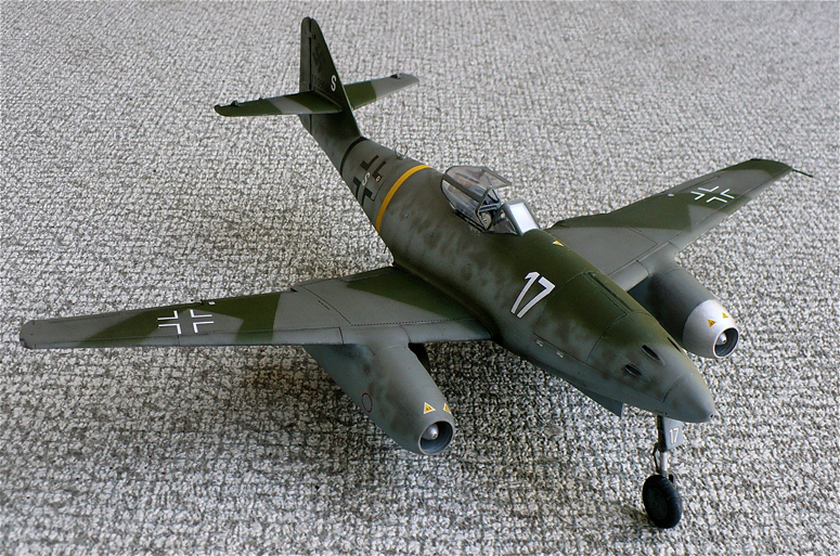
This model was built from the other Trieste II DSV kit. The remnants of two ME 262 jet engines, a TV aerial, the rudder from a HE 177 and various sundries of greebling and wotnot.
The two main things in my opinion that are important when creating post apocalyptic machinery is that it must look like it was put together piece meal, as one would expect to see in a post apocalyptic environment. The second thing is that they must have a face. I feel it gives an addition of character to said model.
Pictures of my other Post Apocalyptic vehicle can be seen here.
Translate
Friday, September 21, 2012
Wednesday, September 19, 2012
Granville P-45 Composite
Here is my composite image of the 1/32 scale Granville P-45 diving out of a blue sky.
Images of the model can be seen here.
Granville P-45
Here are some images a 1/32 scale Granville P-45 B fighter. Built from Lindberg's 1/32 Gee Bee R racer.
This model was based in part off of the Mercenary Graphics drawing and is hypothetical in nature as to its appearance. At present no photographs have come forward as to what these aircraft looked like.
If anyone out there has any photos of these craft I would love to see them.
After the attack on Pearl Harbor the Gee Bee Racer was pressed into service and became the Granville P-45 fighter where it served on the Aleutian Islands and the Panama Canal Zone in 1942, where it gained some success against the Mitsubishi A5M4 (Claude).
This model was based in part off of the Mercenary Graphics drawing and is hypothetical in nature as to its appearance. At present no photographs have come forward as to what these aircraft looked like.
If anyone out there has any photos of these craft I would love to see them.
After the attack on Pearl Harbor the Gee Bee Racer was pressed into service and became the Granville P-45 fighter where it served on the Aleutian Islands and the Panama Canal Zone in 1942, where it gained some success against the Mitsubishi A5M4 (Claude).
Monday, September 17, 2012
Bathyscaphe Trieste II
Here are some images of Viking Models 1/72scale Bathyscaphe Trieste II deep submergence vehicle.
This model has to be one of the worst kits I've ever had the pleasure of building.
I originally purchased this kit back in the mid 90's as it was a neat subject and I love submarines.
When I got the kit home I was depressed to discover that half the parts were missing from the kit.
So as a result I took it back to the hobby shop where I purchased it from. The owner luckily (or so I thought) had another kit, so we decided to have a look only to discover that the same parts were missing from that kit as well. Oh well I thought that's the way things go sometimes and got my refund and thought no more of it.
Little did I know that over the next 15 years the owner of the hobby shop had been trying to get his money back from Viking Models to no avail. He would phone them periodically. The phone would ring but no one would answer.
15 years later I walk into the hobby shop and the owner presents me with 2 Trieste II model kits. Tells me about the failed attempts at trying to contact Viking models and says that if I can build for him I can have the other one. Being the friend he is I agreed.
Well upon inspecting the kit I discovered that Viking Models had an email address. So I decided to take a picture of the 2 kits and wrote out a list of the missing parts and emailed them to Viking Models asking where I might be able to procure the missing parts hoping beyond hope that may have said parts still available even after all these years but I got no response from them, nothing. The email went through but no reply. So for the next 8 months I kept emailing them the same email over and over again but no response. If Viking Models no longer exists then why does their phone ring and their email address still work? However one can only beat a dead horse for so long before one realizes that it's dead.
The only option left remaining for me was to scratch build the missing parts and to take other needed parts from the other kit to complete one kit, which is what I did. So I scratched out the fins, legs, conning tower, blade shrouds,etc.
The main problem with garage kits prior to the 2000's is that they look like garage kits and they build like garage kits. Poorly molded parts and materials being the main culprit (maybe that's why Viking Models refuses to respond). eg: The main hull was molded off center. One does a lot of work to yield only an acceptable result. So here it is for what it's worth the 1/72scale Bathyscaphe Trieste II deep submergence vehicle.
As for what's left of the other kit, I think I'm going to create a fantasy ship of some sort (I have some ideas). It will certainly be a lot more fun than this kit was.
From Wikipedia"
Trieste II (DSV-1) was the successor to Trieste — the United States Navy's first bathyscaphe purchased from its Swiss designers. The original Trieste design was heavily modified by the Naval Electronics Laboratory in San Diego, California and built at the Mare Island Naval Shipyard. Trieste II incorporated the original Terni, Italian-built sphere used in Trieste, after it was made redundant by the new high-pressure sphere cast by the German Krupp Steelworks. The Trieste sphere was suspended from an entirely new float, more seaworthy and streamlined than the original but operating on identical principles. Completed in early 1964, Trieste II was placed on board USNS Francis X. McGraw (T-AK241) and shipped, via the Panama Canal, to Boston.
Commanded by Lt Comdr. John B. Mooney, Jr., with co-pilot Lt. John H. Howland and Capt. Frank Andrews, Trieste II conducted dives in the vicinity of the loss site of Thresher — operations commenced by the first Trieste the year before. She recovered bits of wreckage, positively fixing the remains as that of the lost Thresher, in September 1964.
Between September 1965 and May 1966, Trieste II again underwent extensive modification and conversion at Mare Island Naval Shipyard, but there is no clear record that she was ever operated in that new configuration, i.e., the addition of skegs or outriggers on both sides of the sphere.
During that same time period work was under way on a third configuration of the bathyscaphe. This work resulted in yet a new appearance for the Trieste II, and included the installation of a new pressure sphere, designed for operation to 20,000 feet (6,100 m).
As the bathyscaphe continued her operations as test vehicle for the deep submergence program, she qualified four officers as "hydronauts" — the beginning of a burgeoning oceanographic operation. Trieste II's valuable experience in deep submergence operations has helped in the design and construction of other deep-diving submersibles which could be used in rescuing crews and recovering objects from submarines in distress below levels reachable by conventional methods.
This unique craft was listed only as "equipment" in the Navy inventory until the autumn of 1969. On 1 September 1969, Trieste II was placed in service, with the hull number X-1. Reclassified as a deep submergence vehicle (DSV) on 1 June 1971, Trieste II (DSV-1) continued her active service in the Pacific Fleet into 1980.
The Trieste class DSV were replaced by the Alvin class DSV, as exemplified by the famous Alvin (DSV-2). The Alvins are more capable, more maneuverable, less fragile, but also can not dive as deep, reaching only a maximum of 20,000 feet (for the Sea Cliff (DSV-4)).
Trieste II is now preserved as a museum ship at the Naval Undersea Museum, Keyport, Washington.
This model has to be one of the worst kits I've ever had the pleasure of building.
I originally purchased this kit back in the mid 90's as it was a neat subject and I love submarines.
When I got the kit home I was depressed to discover that half the parts were missing from the kit.
So as a result I took it back to the hobby shop where I purchased it from. The owner luckily (or so I thought) had another kit, so we decided to have a look only to discover that the same parts were missing from that kit as well. Oh well I thought that's the way things go sometimes and got my refund and thought no more of it.
Little did I know that over the next 15 years the owner of the hobby shop had been trying to get his money back from Viking Models to no avail. He would phone them periodically. The phone would ring but no one would answer.
15 years later I walk into the hobby shop and the owner presents me with 2 Trieste II model kits. Tells me about the failed attempts at trying to contact Viking models and says that if I can build for him I can have the other one. Being the friend he is I agreed.
Well upon inspecting the kit I discovered that Viking Models had an email address. So I decided to take a picture of the 2 kits and wrote out a list of the missing parts and emailed them to Viking Models asking where I might be able to procure the missing parts hoping beyond hope that may have said parts still available even after all these years but I got no response from them, nothing. The email went through but no reply. So for the next 8 months I kept emailing them the same email over and over again but no response. If Viking Models no longer exists then why does their phone ring and their email address still work? However one can only beat a dead horse for so long before one realizes that it's dead.
The only option left remaining for me was to scratch build the missing parts and to take other needed parts from the other kit to complete one kit, which is what I did. So I scratched out the fins, legs, conning tower, blade shrouds,etc.
The main problem with garage kits prior to the 2000's is that they look like garage kits and they build like garage kits. Poorly molded parts and materials being the main culprit (maybe that's why Viking Models refuses to respond). eg: The main hull was molded off center. One does a lot of work to yield only an acceptable result. So here it is for what it's worth the 1/72scale Bathyscaphe Trieste II deep submergence vehicle.
As for what's left of the other kit, I think I'm going to create a fantasy ship of some sort (I have some ideas). It will certainly be a lot more fun than this kit was.
From Wikipedia"
Trieste II (DSV-1) was the successor to Trieste — the United States Navy's first bathyscaphe purchased from its Swiss designers. The original Trieste design was heavily modified by the Naval Electronics Laboratory in San Diego, California and built at the Mare Island Naval Shipyard. Trieste II incorporated the original Terni, Italian-built sphere used in Trieste, after it was made redundant by the new high-pressure sphere cast by the German Krupp Steelworks. The Trieste sphere was suspended from an entirely new float, more seaworthy and streamlined than the original but operating on identical principles. Completed in early 1964, Trieste II was placed on board USNS Francis X. McGraw (T-AK241) and shipped, via the Panama Canal, to Boston.
Commanded by Lt Comdr. John B. Mooney, Jr., with co-pilot Lt. John H. Howland and Capt. Frank Andrews, Trieste II conducted dives in the vicinity of the loss site of Thresher — operations commenced by the first Trieste the year before. She recovered bits of wreckage, positively fixing the remains as that of the lost Thresher, in September 1964.
Between September 1965 and May 1966, Trieste II again underwent extensive modification and conversion at Mare Island Naval Shipyard, but there is no clear record that she was ever operated in that new configuration, i.e., the addition of skegs or outriggers on both sides of the sphere.
During that same time period work was under way on a third configuration of the bathyscaphe. This work resulted in yet a new appearance for the Trieste II, and included the installation of a new pressure sphere, designed for operation to 20,000 feet (6,100 m).
As the bathyscaphe continued her operations as test vehicle for the deep submergence program, she qualified four officers as "hydronauts" — the beginning of a burgeoning oceanographic operation. Trieste II's valuable experience in deep submergence operations has helped in the design and construction of other deep-diving submersibles which could be used in rescuing crews and recovering objects from submarines in distress below levels reachable by conventional methods.
This unique craft was listed only as "equipment" in the Navy inventory until the autumn of 1969. On 1 September 1969, Trieste II was placed in service, with the hull number X-1. Reclassified as a deep submergence vehicle (DSV) on 1 June 1971, Trieste II (DSV-1) continued her active service in the Pacific Fleet into 1980.
The Trieste class DSV were replaced by the Alvin class DSV, as exemplified by the famous Alvin (DSV-2). The Alvins are more capable, more maneuverable, less fragile, but also can not dive as deep, reaching only a maximum of 20,000 feet (for the Sea Cliff (DSV-4)).
Trieste II is now preserved as a museum ship at the Naval Undersea Museum, Keyport, Washington.
Sunday, September 16, 2012
Dave Porter's 1978 Ferrari 312
Here are some images of Dave Porter's Tamiya 1/20 scale Gilles Villeneuve's 1978 Ferrari 312 and here in his own words is his description.
This is the great Gilles Villeneuve's 1978 Ferrari
312. I'm sure he had the most exciting drives in the history of F1 in this car.
The model is in 1/20 from Tamiya. I finished it in Testors, Metalizers,
Alclads and Tamiya acrylics and laquers. The decals are from Indycals because
the decals provided in the kit are not up to the task. The race harness is from
"Modelers"
Dave Porter's B - 24 D
Here are some images of Dave Porter's Minicraft 1/72 scale Consolidated B - 24 D Liberator and here in his own words is his description.
Here is a B-24D "Wongo Wongo" that went on the Raid to Ploesti but myteriously crashed off the coast of Corsica. The kit is in 1/72 by Minicraft. It all fits together pretty good but is very sparse on interior detail. I added about fifty parts to help it out a bit. I painted it in Warbirds colors and I used artist oils to weather it.
Saturday, September 15, 2012
Dave Porter's Mitsubishi F1M (Pete)
Here are some images of Dave Porter's Tamiya 1/50 scale Mitsubishi F1M (Pete) float plane finished in acrylics and artist oils.
From Wikipedia"
The Mitsubishi F1M (Allied reporting name "Pete") was a Japanese reconnaissance floatplane of World War II. It was the last biplane type of the Imperial Japanese Navy, with 1,118 built between 1936 and 1944. The Navy designation was "Type Zero Observation Seaplane" not to be confused with the Type Zero Carrier Fighter or the Type Zero Reconnaissance Seaplane.
The F1M1 was powered by the Nakajima Hikari MK1 radial engine, delivering 611 kW (820 hp), a maximum speed of 368 km/h (230 mph) and operating range of up to 1,072 km (670 mi) (when overloaded). It provided the Imperial Japanese Navy with a very versatile operations platform.
Optionally armed with a maximum of three 7.7 mm (.303 in) machine guns (two fixed forward-firing and one flexible rear-firing) and two 60 kg (132 lb) bombs
The F1M was originally built as a catapult-launched reconnaissance float plane, specializing in gunnery spotting. However the "Pete" took on a number of local roles including area-defense fighter, convoy escort, bomber, anti-submarine, maritime patrol, rescue and transport. The type fought dogfights in the Aleutians, the Solomons and several other theaters. See also PT 34 sunk 9 April 1942 by "Petes".
Thursday, September 13, 2012
Messerschmitt ME 262 A 1a
Here are some images of Trumpeter's 1/32 scale Messerschmitt ME 262 A 1a.
From Wikipedia"
The Messerschmitt Me 262 Schwalbe ("Swallow") was the world's first operational jet-powered fighter aircraft. Design work started before World War II began but engine problems prevented the aircraft from attaining operational status with the Luftwaffe until mid-1944. Compared with Allied fighters of its day, including the British jet-powered Gloster Meteor, it was much faster and better armed One of the most advanced aviation designs in operational use during World War II, the Me 262 was used in a variety of roles, including light bomber, reconnaissance and even experimental night fighter versions.
Me 262 pilots claimed a total of 542 Allied kills (although higher claims are sometimes made) against the loss of only about 100 Me 262s in the air. The Allies countered its potential effectiveness in the air by relentlessly attacking the aircraft on the ground and while they were taking off or landing. Maintenance problems and a lack of fuel during the deteriorating late-war situation also reduced the effectiveness of the aircraft as a fighting force. In the end, the Me 262 had a negligible impact on the course of the war as a result of its late introduction and the consequently small numbers that were deployed in operational service. The Me 262 influenced the designs of post-war aircraft such as the North American F-86 Sabre and Boeing B-47 Stratojet.
Several years before World War II, the Germans foresaw the great potential for aircraft of a British invention: the jet engine, invented by Frank Whittle in 1928. As they were in the middle of a great military build up which would lead to war, they ignored the various patents that Whittle had in effect and simply took the idea and developed it into a very advanced fighter aircraft. As a result, the Me 262 was already being developed as Projekt 1065 (P.1065) before the start of World War II. Plans were first drawn up in April 1939, and the original design was very similar to the plane that eventually entered service. The progression of the original design into service was delayed greatly by technical issues involving the new jet engine. Funding for the jet program was also initially lacking as many high-ranking officials thought the war could easily be won with conventional aircraft. Among those were: Hermann Göring, head of the Luftwaffe, who cut the engine development program to just 35 engineers in February 1940; Willy Messerschmitt, who desired to maintain mass production of the piston-powered Bf 109 and the projected Me 209; and Major General Adolf Galland, who supported Messerschmitt through the early development years, flying the Me 262 himself on 22 April 1943. By that time, problems with engine development had slowed production of the aircraft considerably. One particularly acute problem arose with the lack of an alloy with a melting point high enough to endure the high temperatures involved, a problem that by the end of the war had not been adequately resolved.
The project aerodynamicist on the design of the Me 262 was Ludwig Bölkow, later a prominent figure in the post-World War II development of the German aircraft industry. He initially designed the wing using NACA airfoils modified with an elliptical nose section. Later in the design process, these were changed to AVL derivatives of NACA airfoils, the NACA 00011-0.825-35 being used at the root and the NACA 00009-1.1-40 at the tip. The elliptical nose derivatives of the NACA airfoils were used on the horizontal and vertical tail surfaces. Wings were single-spar cantilever construction, with stressed skins, varying from 3 mm (0.12 in) thick at the root to 1 mm (0.039 in) at the tip. The wings were fastened to the fuselage at four points, using a pair of 20 mm (0.79 in) and forty-two 8 mm (0.31 in) bolts.
In mid-1943, Adolf Hitler envisioned the Me 262 as an offensive ground-attack/bomber rather than a defensive interceptor. The configuration of a high-speed, light-payload Schnellbomber ("Fast Bomber") was intended to penetrate enemy airspace during the expected Allied invasion of France. His edict resulted in the development of (and concentration on) the Sturmvogel variant. It is debatable to what extent Hitler's interference extended the delay in bringing the Schwalbe into operation. Albert Speer, then Minister of Armaments and War Production, claimed in his memoirs that Hitler originally had blocked mass production of the Me 262 before agreeing in early 1944. He rejected arguments that the aircraft would be more effective as a fighter against Allied bombers destroying large parts of Germany, and wanted it as a bomber for revenge attacks. According to Speer, Hitler felt its superior speed compared to other fighters of the era meant it could not be attacked and so preferred it for high altitude straight flying.
Although the Me 262 is often referred to as a "swept wing" design, the production Me 262 had a leading edge sweep of only 18.5°, too slight to achieve any significant advantage in increasing the critical Mach number Sweep was added after the initial design of the aircraft, when the engines proved to be heavier than originally expected, primarily to position the center of lift properly relative to the centre of mass. On 1 March 1940, instead of moving the wing backward on its mount, the outer wing was repositioned slightly aft; the trailing edge of the midsection of the wing remained unswept. Based on data from the AVA Göttingen and wind tunnel results, the middle section's leading edge was later swept to the same angle as the outer panels.
From Wikipedia"
The Messerschmitt Me 262 Schwalbe ("Swallow") was the world's first operational jet-powered fighter aircraft. Design work started before World War II began but engine problems prevented the aircraft from attaining operational status with the Luftwaffe until mid-1944. Compared with Allied fighters of its day, including the British jet-powered Gloster Meteor, it was much faster and better armed One of the most advanced aviation designs in operational use during World War II, the Me 262 was used in a variety of roles, including light bomber, reconnaissance and even experimental night fighter versions.
Me 262 pilots claimed a total of 542 Allied kills (although higher claims are sometimes made) against the loss of only about 100 Me 262s in the air. The Allies countered its potential effectiveness in the air by relentlessly attacking the aircraft on the ground and while they were taking off or landing. Maintenance problems and a lack of fuel during the deteriorating late-war situation also reduced the effectiveness of the aircraft as a fighting force. In the end, the Me 262 had a negligible impact on the course of the war as a result of its late introduction and the consequently small numbers that were deployed in operational service. The Me 262 influenced the designs of post-war aircraft such as the North American F-86 Sabre and Boeing B-47 Stratojet.
Several years before World War II, the Germans foresaw the great potential for aircraft of a British invention: the jet engine, invented by Frank Whittle in 1928. As they were in the middle of a great military build up which would lead to war, they ignored the various patents that Whittle had in effect and simply took the idea and developed it into a very advanced fighter aircraft. As a result, the Me 262 was already being developed as Projekt 1065 (P.1065) before the start of World War II. Plans were first drawn up in April 1939, and the original design was very similar to the plane that eventually entered service. The progression of the original design into service was delayed greatly by technical issues involving the new jet engine. Funding for the jet program was also initially lacking as many high-ranking officials thought the war could easily be won with conventional aircraft. Among those were: Hermann Göring, head of the Luftwaffe, who cut the engine development program to just 35 engineers in February 1940; Willy Messerschmitt, who desired to maintain mass production of the piston-powered Bf 109 and the projected Me 209; and Major General Adolf Galland, who supported Messerschmitt through the early development years, flying the Me 262 himself on 22 April 1943. By that time, problems with engine development had slowed production of the aircraft considerably. One particularly acute problem arose with the lack of an alloy with a melting point high enough to endure the high temperatures involved, a problem that by the end of the war had not been adequately resolved.
The project aerodynamicist on the design of the Me 262 was Ludwig Bölkow, later a prominent figure in the post-World War II development of the German aircraft industry. He initially designed the wing using NACA airfoils modified with an elliptical nose section. Later in the design process, these were changed to AVL derivatives of NACA airfoils, the NACA 00011-0.825-35 being used at the root and the NACA 00009-1.1-40 at the tip. The elliptical nose derivatives of the NACA airfoils were used on the horizontal and vertical tail surfaces. Wings were single-spar cantilever construction, with stressed skins, varying from 3 mm (0.12 in) thick at the root to 1 mm (0.039 in) at the tip. The wings were fastened to the fuselage at four points, using a pair of 20 mm (0.79 in) and forty-two 8 mm (0.31 in) bolts.
In mid-1943, Adolf Hitler envisioned the Me 262 as an offensive ground-attack/bomber rather than a defensive interceptor. The configuration of a high-speed, light-payload Schnellbomber ("Fast Bomber") was intended to penetrate enemy airspace during the expected Allied invasion of France. His edict resulted in the development of (and concentration on) the Sturmvogel variant. It is debatable to what extent Hitler's interference extended the delay in bringing the Schwalbe into operation. Albert Speer, then Minister of Armaments and War Production, claimed in his memoirs that Hitler originally had blocked mass production of the Me 262 before agreeing in early 1944. He rejected arguments that the aircraft would be more effective as a fighter against Allied bombers destroying large parts of Germany, and wanted it as a bomber for revenge attacks. According to Speer, Hitler felt its superior speed compared to other fighters of the era meant it could not be attacked and so preferred it for high altitude straight flying.
Although the Me 262 is often referred to as a "swept wing" design, the production Me 262 had a leading edge sweep of only 18.5°, too slight to achieve any significant advantage in increasing the critical Mach number Sweep was added after the initial design of the aircraft, when the engines proved to be heavier than originally expected, primarily to position the center of lift properly relative to the centre of mass. On 1 March 1940, instead of moving the wing backward on its mount, the outer wing was repositioned slightly aft; the trailing edge of the midsection of the wing remained unswept. Based on data from the AVA Göttingen and wind tunnel results, the middle section's leading edge was later swept to the same angle as the outer panels.
Thursday, September 6, 2012
McLaren M8A 1968
I tried something different with this model. Instead of painting the body of this car, all I did was apply a couple of coats of gloss varnish and it turned out great.
From the instructions"
1966 saw the inauguration of the Canadian-American Challenge Cup (CAN-AM), which raced two seater open top machines with unlimited engine displacements. Although held domestically, this unique series saw many F1drivers in attendance and quickly gained popularity due to the dynamic performances of the high powered machines. It became one of the most exciting race categories after F1 GP and the World Sports Car Chamionship. Founded by F1 driver Bruce McLaren in 1963 Bruce McLaren Motor Racing raced CAN AM and F1 GP from 1966. The 1966 CAN-AM season saw Bruce McLaren drive the McLaren M1B to the third place overall ranking. The following year he drove the M6A and won the championship, which led to the teams succesful period.
In 1968, the team entered the M8A which was lighter, had enhanced aerodynamics, and adapted the same monocoque structure of other F1 machines with the engine firmly connected to the rear bulkhead. The wedge-shaped body producd the increased downforce effect and featured air intakes with NASA ducts.
It was powered by a 620 hp Chevrolet V8 7-liter engine with eight 40cm long air funnels. In this six race series Denny Hulme and Bruce McLaren drove the M8A and took 3 and 1 wins respectively to dominate the season. Not resting on their laurels, the M8A continually evolved with the M8B, M8D, and M8F respectively. Despite the tragic test drive accident that involved Bruce McLaren in 1970, the team swept the CAN-AM, taking 5 consecutive championships from 1967 to 1971.
Tuesday, September 4, 2012
Shinkai (しんかい) 6500 Composite
Here is my composite image of Bandai's 1/48 scale Jamstec Shinkai 6500 Manned Research Submersible in a deep ocean setting.
Images of the model can be seen here.
Monday, September 3, 2012
Roman Trireme
Here are some images of Zvezda's 1/72 scale Roman Trireme.
Normally I refuse to build plastic ship kits but this kit was so interesting I couldn't resist.
One thing I've noticed about this kit is the use of 19th century rigging and deck planking.
Oh well these ships are mostly conjecture anyway.
From Wikipedia"
A trireme (derived from Latin: "tres remi:" "three-oar;" Greek Τριήρης, literally "three-oarer") was an ancient vessel and a type of galley, a Hellenistic-era warship that was used by the ancient maritime civilizations of the Mediterranean, especially the Phoenicians, ancient Greeks and Romans.
The trireme derives its name from its three rows of oars on each side, manned with one man per oar. The early trireme was a development of the penteconter, an ancient warship with a single row of 25 oars on each side, and of the bireme (Greek: διήρης), a warship with two banks of oars, probably of Phoenician origin. As a ship it was fast and agile, and became the dominant warship in the Mediterranean from the 7th to the 4th centuries BC, when they were largely superseded by the larger quadriremes and quinqueremes. Triremes played a vital role in the Persian Wars, the creation of the Athenian maritime empire, and its downfall in the Peloponnesian War.
In English, no differentiation is made between the Greek triērēs and the Latin triremis. This is sometimes a source of confusion, as in other languages these terms refer to different styles of ships. Though the term today is used almost exclusively for ancient warships, modern historians also refer to medieval and early modern galleys with three banks of oars per side as triremes. The rowing arrangement of these differed considerably, though, since knowledge of the multi-level structure of the original triremes was lost some time during Late Antiquity.
The exact origin of the trireme is uncertain and debated, as our evidence comes from literary sources, depictions in reliefs and pottery fragments, which are open to misinterpretations. Depictions of two-tiered ships (biremes), with or without the parexeiresia (the outriggers, see below), are common in 8th century BC vases and pottery fragments, and it is at the end of that century that the first references to three-tiered ships are found. According to Thucydides, the trireme was introduced to Greece by the Corinthians in the late 8th century BC, and the Corinthian Ameinocles built four such ships for the Samians. Although this was interpreted by later writers, Pliny and Diodorus, to mean that triremes were invented in Corinth, it is likely that the earliest three-tiered warships originated in Phoenicia. Fragments from an 8th century relief at the Assyrian capital of Nineveh depicting the fleets of Tyre and Sidon have been interpreted as depicting two- and three-level warships, fitted with rams. The 2nd century Christian scholar Clement of Alexandria, drawing on earlier works, explicitly attributes the invention of the trireme (trikrotos naus, "three-tiered ship") to the Sidonians.
Based on all archeological evidence, the design of trireme surely pushed the technological limits of the ancient world. After gathering the proper timbers and materials it was time to consider the fundamentals of the trireme design. These fundamentals included accommodations, propulsion, weight and waterline, center of gravity and stability, strength, and feasibility. All of these variables are dependent on one another; however a certain area may be more important than another depending on the purpose of the ship.
The arrangement and number of oarsmen is the first deciding factor in the size of the ship. For a ship to travel at high speeds would require a high oar-gearing, which is the ratio between the outboard length of an oar and the inboard length; it is this arrangement of the oars which is unique and highly effective for the trireme. The ports would house the oarsmen with a minimal waste of space. There would be three files of oarsmen on each side tightly but workably packed by placing each man outboard of, and in height overlapping, the one below, provided that thalamian tholes were set inboard and their ports enlarged to allow oar movement. Thalamian is the English term for the Greek word, thalamios, which was the name of the oarsmen in the lowest file of the triereis; zygian is the English term for the Greek word, zygios, which were the oarsmen in the middle file of the triereis, and thranite is the English term for the Greek word, thranites, which were the oarsmen in the uppermost file of the triereis. Tholes were pins that acted as fulcrums to the oars that allowed them to move. The center of gravity of the ship is low because of the overlapping formation of the files that allow the ports to remain closer to the ships walls. A lower center of gravity would provide adequate stability.
The trireme was constructed to maximize all traits of the ship to the point where if any changes were made the design would be compromised. Speed was maximized to the point where any less weight would have resulted in considerable losses to the ship's integrity. The center of gravity was placed at the lowest possible position where the Thalamian tholes were just above the waterline which retained the ships resistance to waves and the possible rollover. If the center of gravity were placed any higher, the additional beams needed to restore stability would have resulted in the exclusion of the Thalamian tholes due to the reduced hull space. The purpose of the area just below the center of gravity and the waterline known as the hypozomata was to allow bending of the hull when faced with up to 90kN of force. The calculations of forces that could have been absorbed by the ship are arguable because there is not enough evidence to confirm the exact process of jointing used in ancient times. In a modern reconstruction of the ship, a polysulphide sealant was used to compare to the caulking that evidence suggests was used; however this is also argued because there is simply not enough evidence to authentically reproduce the triereis seams.
Triremes required a great deal of upkeep in order to stay afloat, as references to the replacement of ropes, sails, rudders, oars and masts in the middle of campaigns suggest. They also would become waterlogged if left in the sea for too long. In order to prevent this from happening, ships would have to be pulled from the water during the night. The use of lightwoods meant that the ship could be carried ashore by as few as 140 men. Beaching the ships at night however, would leave the troops vulnerable to surprise attacks. While well-maintained triremes would last up to 25 years, during the Peloponnesian War, Athens had to build nearly 20 triremes a year to maintain their fleet of 300.
The Athenian trireme had two great cables of about 47 mm in diameter and twice the ship's length called hypozomata (undergirding), and carried two spares. They were possibly rigged fore and aft from end to end along the middle line of the hull just under the main beams and tensioned to 13.5 tonnes force. The hypozomata were considered important and secret: their export from Athens was a capital offence. This cable would act as a stretched tendon straight down the middle of the hull, and would have prevented hogging. Additionally, hull plank butts would remain in compression in all but the most severe sea conditions, reducing working of joints and consequent leakage. The hypozomata would also have significantly braced the structure of the trireme against the stresses of ramming, giving it an important advantage in combat.
Normally I refuse to build plastic ship kits but this kit was so interesting I couldn't resist.
One thing I've noticed about this kit is the use of 19th century rigging and deck planking.
Oh well these ships are mostly conjecture anyway.
From Wikipedia"
A trireme (derived from Latin: "tres remi:" "three-oar;" Greek Τριήρης, literally "three-oarer") was an ancient vessel and a type of galley, a Hellenistic-era warship that was used by the ancient maritime civilizations of the Mediterranean, especially the Phoenicians, ancient Greeks and Romans.
The trireme derives its name from its three rows of oars on each side, manned with one man per oar. The early trireme was a development of the penteconter, an ancient warship with a single row of 25 oars on each side, and of the bireme (Greek: διήρης), a warship with two banks of oars, probably of Phoenician origin. As a ship it was fast and agile, and became the dominant warship in the Mediterranean from the 7th to the 4th centuries BC, when they were largely superseded by the larger quadriremes and quinqueremes. Triremes played a vital role in the Persian Wars, the creation of the Athenian maritime empire, and its downfall in the Peloponnesian War.
In English, no differentiation is made between the Greek triērēs and the Latin triremis. This is sometimes a source of confusion, as in other languages these terms refer to different styles of ships. Though the term today is used almost exclusively for ancient warships, modern historians also refer to medieval and early modern galleys with three banks of oars per side as triremes. The rowing arrangement of these differed considerably, though, since knowledge of the multi-level structure of the original triremes was lost some time during Late Antiquity.
The exact origin of the trireme is uncertain and debated, as our evidence comes from literary sources, depictions in reliefs and pottery fragments, which are open to misinterpretations. Depictions of two-tiered ships (biremes), with or without the parexeiresia (the outriggers, see below), are common in 8th century BC vases and pottery fragments, and it is at the end of that century that the first references to three-tiered ships are found. According to Thucydides, the trireme was introduced to Greece by the Corinthians in the late 8th century BC, and the Corinthian Ameinocles built four such ships for the Samians. Although this was interpreted by later writers, Pliny and Diodorus, to mean that triremes were invented in Corinth, it is likely that the earliest three-tiered warships originated in Phoenicia. Fragments from an 8th century relief at the Assyrian capital of Nineveh depicting the fleets of Tyre and Sidon have been interpreted as depicting two- and three-level warships, fitted with rams. The 2nd century Christian scholar Clement of Alexandria, drawing on earlier works, explicitly attributes the invention of the trireme (trikrotos naus, "three-tiered ship") to the Sidonians.
Based on all archeological evidence, the design of trireme surely pushed the technological limits of the ancient world. After gathering the proper timbers and materials it was time to consider the fundamentals of the trireme design. These fundamentals included accommodations, propulsion, weight and waterline, center of gravity and stability, strength, and feasibility. All of these variables are dependent on one another; however a certain area may be more important than another depending on the purpose of the ship.
The arrangement and number of oarsmen is the first deciding factor in the size of the ship. For a ship to travel at high speeds would require a high oar-gearing, which is the ratio between the outboard length of an oar and the inboard length; it is this arrangement of the oars which is unique and highly effective for the trireme. The ports would house the oarsmen with a minimal waste of space. There would be three files of oarsmen on each side tightly but workably packed by placing each man outboard of, and in height overlapping, the one below, provided that thalamian tholes were set inboard and their ports enlarged to allow oar movement. Thalamian is the English term for the Greek word, thalamios, which was the name of the oarsmen in the lowest file of the triereis; zygian is the English term for the Greek word, zygios, which were the oarsmen in the middle file of the triereis, and thranite is the English term for the Greek word, thranites, which were the oarsmen in the uppermost file of the triereis. Tholes were pins that acted as fulcrums to the oars that allowed them to move. The center of gravity of the ship is low because of the overlapping formation of the files that allow the ports to remain closer to the ships walls. A lower center of gravity would provide adequate stability.
The trireme was constructed to maximize all traits of the ship to the point where if any changes were made the design would be compromised. Speed was maximized to the point where any less weight would have resulted in considerable losses to the ship's integrity. The center of gravity was placed at the lowest possible position where the Thalamian tholes were just above the waterline which retained the ships resistance to waves and the possible rollover. If the center of gravity were placed any higher, the additional beams needed to restore stability would have resulted in the exclusion of the Thalamian tholes due to the reduced hull space. The purpose of the area just below the center of gravity and the waterline known as the hypozomata was to allow bending of the hull when faced with up to 90kN of force. The calculations of forces that could have been absorbed by the ship are arguable because there is not enough evidence to confirm the exact process of jointing used in ancient times. In a modern reconstruction of the ship, a polysulphide sealant was used to compare to the caulking that evidence suggests was used; however this is also argued because there is simply not enough evidence to authentically reproduce the triereis seams.
Triremes required a great deal of upkeep in order to stay afloat, as references to the replacement of ropes, sails, rudders, oars and masts in the middle of campaigns suggest. They also would become waterlogged if left in the sea for too long. In order to prevent this from happening, ships would have to be pulled from the water during the night. The use of lightwoods meant that the ship could be carried ashore by as few as 140 men. Beaching the ships at night however, would leave the troops vulnerable to surprise attacks. While well-maintained triremes would last up to 25 years, during the Peloponnesian War, Athens had to build nearly 20 triremes a year to maintain their fleet of 300.
The Athenian trireme had two great cables of about 47 mm in diameter and twice the ship's length called hypozomata (undergirding), and carried two spares. They were possibly rigged fore and aft from end to end along the middle line of the hull just under the main beams and tensioned to 13.5 tonnes force. The hypozomata were considered important and secret: their export from Athens was a capital offence. This cable would act as a stretched tendon straight down the middle of the hull, and would have prevented hogging. Additionally, hull plank butts would remain in compression in all but the most severe sea conditions, reducing working of joints and consequent leakage. The hypozomata would also have significantly braced the structure of the trireme against the stresses of ramming, giving it an important advantage in combat.
Thursday, August 30, 2012
Ironman One From Marooned Composite
Here is my composite image of my kit bash Ironman One from the 1969 movie Marooned orbiting the Earth.
Images of the model can be seen here.
Ironman One From Marooned
Here are some images of my kit bash Ironman One from the 1969 movie Marooned.
Built from Dragon Models 1/48 scale Apollo 11 Command/Service Module.
I couldn't swear to its accuracy as there doesn't seem to be very much information on it.
Still I think it gives a reasonable facsimile.
From Wikipedia"
Marooned is a 1969 American film directed by John Sturges and starring Gregory Peck, Richard Crenna, David Janssen, James Franciscus, and Gene Hackman.
The film was released less than four months after the Apollo 11 moon landing and was tied to the public fascination with the event. It won an Academy Award for Visual Effects.
It was based on the 1964 novel of the same name by Martin Caidin; however, while the original novel was based on the single-pilot Mercury program, the film depicted an Apollo Command/Service Module with three astronauts and a space station resembling Skylab. Caidin acted as technical adviser and updated the novel, incorporating appropriate material from the original version.
Three American astronauts—commander Jim Pruett (Crenna), "Buzz" Lloyd (Hackman), and Clayton "Stoney" Stone (Franciscus)—are the first crew of an experimental space station. While returning to Earth, the main engine on the Apollo spacecraft Ironman One fails. Mission Control determines that Ironman does not have enough backup thruster capability to initiate atmospheric reentry, or to re-dock with the station and wait for rescue. The crew is marooned in orbit.
NASA debates whether a rescue flight can reach the crew before their oxygen runs out in approximately two days. There are no backup launch vehicles or rescue systems available at Kennedy Space Center and NASA director Charles Keith (Peck) opposes using an experimental Air Force X-RV lifting body that would be launched on a Titan IIIC booster; neither the spacecraft nor the booster is man-rated, and there is insufficient time to put a new manned NASA mission together. Even though a booster is already on the way to nearby Cape Canaveral Air Force Station for an already-scheduled Air Force launch, many hundreds of hours of preparation, assembly, and testing would be necessary.
Ted Dougherty (Janssen), the Chief Astronaut, opposes Keith and demands that something be done. The President agrees with Dougherty and tells Keith that failing to try a rescue mission will kill public support for the manned space program. The President tells Keith that money is no factor; "whatever you need, you've got it".
While the astronauts' wives (Lee Grant, Mariette Hartley, and Nancy Kovack) agonize over the fates of their husbands, all normal checklist procedures are bypassed to prepare the X-RV for launch. A hurricane headed for the launch area threatens to cancel the mission. However, the eye of the storm passes over the Cape at the last minute during a launch window, permitting a launch with Dougherty aboard.
There is insufficient oxygen left for all three astronauts to survive until Dougherty arrives. There is possibly enough for two. Pruett and his crew then debate what to do. Stone tries to reason that they can somehow survive. Lloyd offers to leave since he is "using up most of the oxygen anyway", but Pruett overrides him. He orders everyone into their spacesuits then leaves the ship, ostensibly to attempt repairs. When Lloyd realizes what Pruett is really intending, he attempts to go after him. Before he can reach Pruett, the latter sacrifices himself by tearing open his space suit, and his body drifts away into space. With Pruett gone, Stone takes command.
A Soviet spacecraft suddenly appears and its cosmonaut tries to make contact. It can do nothing but deliver oxygen since the Soviet ship is too small to carry additional passengers. Stone and Lloyd, suffering oxygen deprivation, cannot understand the cosmonaut's gestures or obey Keith's orders.
Dougherty arrives and he and the cosmonaut transfer the two surviving and mentally dazed Ironman astronauts into the rescue ship. Both the Soviet ship and the X-RV return to Earth, and the final scene fades out with a view of the abandoned Ironman One adrift in orbit.
Wednesday, August 29, 2012
SLC 200 Maiale Human Torpedo
Here are some images of Model Victoria's 1/35 scale SLC 200 Maiale Human Torpedo built for a client.
The base was created by me.
From Wikipedia"
Human torpedoes or manned torpedoes are a type of rideable submarine used as secret naval weapons in World War II. The basic design is still in use today; they are a type of diver propulsion vehicle.
The name was commonly used to refer to the weapons that Italy, and later Britain, deployed in the Mediterranean and used to attack ships in enemy harbours. A group of a dozen countries used the human torpedo, from Italy and Great Britain to Argentina and Egypt, and there are some museums and movies dedicated to this naval weapon. The human torpedo concept is used recreationally for sport diving.
The first human torpedo (the Italian Maiale) was electrically propelled, with two crewmen in diving suits riding astride. They steered the torpedo at slow speed to the enemy ship. The detachable warhead was then used as a limpet mine. They then rode the torpedo away.
In operation, the Maiale torpedo was carried by another vessel (usually a normal submarine), and launched near the target. Most manned torpedo operations were at night and during the new moon to cut down the risk of being seen.
The idea was successfully applied by the Italian navy (Regia Marina) early in World War II and then copied by the British when they discovered the Italian operations. The official Italian name for their craft was Siluro a Lenta Corsa (SLC or "Slow-running torpedo"), but the Italian operators nicknamed it maiale (Italian for "pig"; plural maiali) because it was difficult to steer. The British copies were named "chariots".
A typical manned torpedo has a propeller and hydroplanes at the rear, side hydroplanes in front, and a control panel and controls for its front rider. It usually has two riders who sit facing forwards. It has navigation aids such as a compass, and nowadays modern aids such as sonar and GPS positioning and modulated ultrasound communications gear. It may have an air (or other breathing gas) supply so its riders do not have to drain their own apparatus while they are riding it. In some the riders' seats are enclosed; in others the seats are open at the sides as in sitting astride a horse. The seat design includes room for the riders' swimfins (if used). There are flotation tanks (typically four: left fore, right fore, left aft, right aft), which can be flooded or blown empty to adjust buoyancy and attitude.
Monday, August 27, 2012
TIE Fighter, TIE Interceptor Composites
Here are my composite images of Fine Molds 1/72 TIE Fighter and TIE Interceptor from Star Wars.
The TIE Fighter is flying past the moon Tethys while the TIE Interceptor is flying past the moon Mimas.
While both are moons of Saturn they also bare a similarity to the Death Star.
Images of the TIE Fighter can be seen here.
Subscribe to:
Posts (Atom)